dr4wbck
The Idea
requirements
-
size for painting a3 paper
-
capstan drive
-
h bot for movement
-
easily to assemble / disassemble
- removable thread of the capstan drive
Initially, our Idea was to build a drawing machine similar to the AxiDraw, but with a capstan drive instead of a belt for driving. We just learned about this type of drive in the lecture and were eager try it out. The motion system would be an H-bot.
For the capstan drive, we took much inspiration from the UrumbotXY 2.0.
First, we met and thought about how to build the machine in general. We decided to use aluminum extrusions and wheels as linear guides. We made some initial sketches to better understand, how the machine whould look like and what parts we would need.
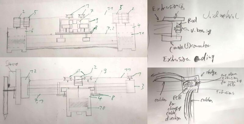
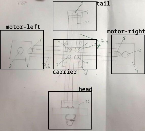
Here you can see the inital concept. The wheels for the linear guide as well as the v-wheels for guiding the rope are placed on the middle carriage and the rope is fixated at the head.
We split the work into the following sub tasks.
- Trying out RAMPS (a kit containing an Arduino for the firmware and drivers) and get it working with Printrun.
- Designing the parts for the tail and the motor mounts.
- Designing a head with a Pen holder and a mechanism to lift it.
- Producing and testing the prototypes and the parts needed.
Initial Design
- many things we modeled ourselves, but we also found models online we used for standard components.
The initial design we kept simple so we could produce them fast and test out the mechanism. We built a simple motor bracket for connecting the motor to the extrusion:
We printed the capstan and pulley from the UrumbotXY 2.0 as well as a simple head.
The carriage we already had as a metal part. It was very sturdy.
Here we needed to be carefull with the screws.
But the wheels for the second axis where on top of the other wheels, which we couldn't implement and Ferdi advised against it.
The tail was designed with only one wheel, which may have bin one cause for our problem.
Then we redesigned it to use both metall carriage, which was pretty sturdy. Also we used eccentric screws to tighten the rope.
Then we designed a head for initialy screw down and tighten the rope.
Also we produced a wire chain to connect the head with the board. In the end we noticed, that the chain was not that sturdy and was not that usable for our machine -.-.
First Assembly
- Capstion Line muss auf einer ebene sein
After designing and printing, we assambled everything...
... cut threads, screwed everything down, assambled the capston drive rope...
... and tried to operate it manually:
yay :D
And it worked nicely :P
Continuation & Redesign
design changes
- removing 9 to place v bearings on same level as vertical extrusion
- to do that we have to put v bearings at the end of the extrusion caps
- do not use motor end caps but use metal or 3d printed plastic caps. ask ferdi, maybe also acrylic
When operating manually, we needed to hold it down so that it is stable, which was the first thing we improved.
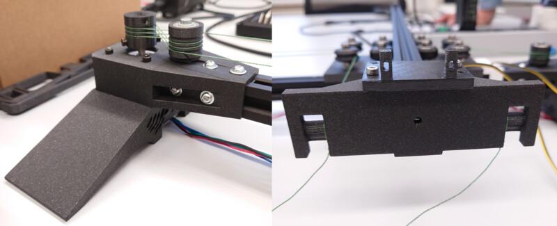
First just making a little angle in the motor bracket improved it a lot but still was oscillating...
... so we created a sideway stabilisation, which then was pretty stable.
Here the head and the initial design for lifting holding and adjusting the pen.
Then we inkluded in the head and on the side an endstop for executing g-code.
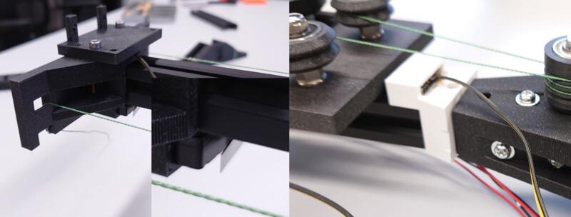
And also a never produced new cariage for mounting the cable chains for the head.
Lessons Learned
- distributing the work in a team is hard
- also finding parts, that can be operated on parallel is not that easy
- nothings works out as expected and things that can go wrong, will go wrong (as told so before)
- we should have partitioned our time more efficiently, then we whould have had a good working product on time and not spend time on little, not necessary things
Setting up the Firmware
Ferdi's Tipps:
Stepper Motor Driver Voltage (Vref) Adjustment Guide for RAMPS 1.4
⚠️ Safety First
Power Off before adjusting.
Use a multimeter (DC 0-2V range).
Ensure proper heatsinks/fans are installed.
🔧 How to Adjust Vref
Locate the potentiometer on each driver.
Connect multimeter:
Black probe → RAMPS ground (e.g., power supply negative)
Red probe → Potentiometer
Adjust screw:
Clockwise → Increase voltage
Counter-clockwise → Decrease voltage
📊 Recommended Vref Values
Calculation Formulas
Driver	Formula
A4988	Vref = Imax × 0.7
DRV8825	Vref = Imax × 0.5
TMC2xxx	Configure via UART
Common Presets (Volts)
Motor Current	A4988	DRV8825
1.0A	0.7V	0.5V
1.5A	1.05V	0.75V
2.0A	1.4V	1.0V
🛠 Troubleshooting
Symptom	Solution
Skipping steps	Slightly ↑ Vref
Overheating	↓ Vref + check cooling
Grinding noise	Check current + wiring
💡 Pro Tips
Start with lower values and test.
For TMC drivers, use software configuration.
Label adjusted drivers with a sharpie.
📌 Always verify motor specs in their datasheet!
Die Motor-Kabel identifiyiert Ihr, indem ihr erstmal die beiden paare identifiziert. Dazu könnt ihr zwei Kabel zusammendrehen (z.B. rot+grün) und schauen ob sich der Motor dann schwerer drehen lässt. Sobald Ihr ein paar gefunden habt, ist das andere das zweite Paar (schwarz gelb). Dann schraubt ihr zuerst Paar1 und dann Paar2 an die vier Klemmen z.B. rot, grün, schwarz, gelb. Wenn der Motor dann falsch rum dreht, invertiert Ihr ein Paar. grün, rot, schwarz, gelb. Ihr könnt aber auch einfach bis Sonntag warten wenn ich wieder da bin.
even more tipps: Hi! Some Tipps for the ramps board:
jakob checked:
notation: ij (pair i, cable j)
find out pairs: measuring current. current is induced when turning if both are connected to one coil, current can be measured
pairs are:
in the end we want to have order
stepper motors behave in the following way:
procedure: align pairs next to each other, check if the motor turns right way. if not: change one of the pairs
what is right direction? we will find out when running everything, but one can also change that in software
setting all jumpers to do 1/16th microsteps: https://reprap.org/wiki/RAMPS_1.4#Drivers
connect motor to x
end stops. man will min und max end stops für z. für x und y reicht min.
adjust current limit: https://www.pololu.com/blog/484/video-setting-the-current-limit-on-pololu-stepper-motor-driver-carriers
installing printrun
installing marlin using platformio
getting it to run. tstraight forward
add servo
corexy einstellen
waiting for machine to be finished
now transferring to corexy
setting corexy and try if we have to change something.
works the same.
switching axes: rotate one socket of the two
switching direction: switch motors
homing
steps calibrieren:
Getting it Running
#define BAUDRATE 250000
Determine Steps per Millimeter
// Enable one of the options below for CoreXY, CoreXZ, or CoreYZ kinematics,
// either in the usual order or reversed
#define COREXY
//#define CoreXZ
//#define COREYZ
//#define COREYX
//#define COREZX
//#define COREZY
/**
 * Default Axis Steps Per Unit (linear=steps/mm, rotational=steps/deg)
 * Override with M92
 * X, Y, Z [, I [, J {, K...]]], E0 [, E1[, E2...]]
 */
#define DEFAULT_AXIS_STEPS_PER_UNIT { 102, 102, 400, 500 }
Homing
Generate toolpath using inkscape
References
Urumbu Drivers
- Urumbu
- Urumbu further work
- sampo, using Urumbu
- OSAP web framework for talking with usb-driven hardware modules (e.g. motors), shoving everything you would make on pcbs onto the desktop for rapid prototyping. overkill for our project.
- Urumbu_IO
- UrumbubotXY 2.0
Capstan Drive
Other
- cable carriers 3d printable
- flexible-XYstage
- pen holder:
- http://www.makelangelo.com/
- https://wiki.opensourceecology.org/wiki/Ferdi
- motor
- cable carrier
- grabcad
Reflection
- working in a team was difficult...