dr4wbck
Idea
We wanted to build a drawing bot. We wanted it to be transportable to bring it to festivals. Assembly and Disassembly should be easy. Other drawing bots we found are listed below.
Most inspiration we drew from the AxiDraw, but we decided to use a capstan drive instead of a belt for driving. We just learned about this type of drive in the lecture and were eager try it out. The motion system would be an H-bot.
For the capstan drive, we took much inspiration from the UrumbotXY 2.0.
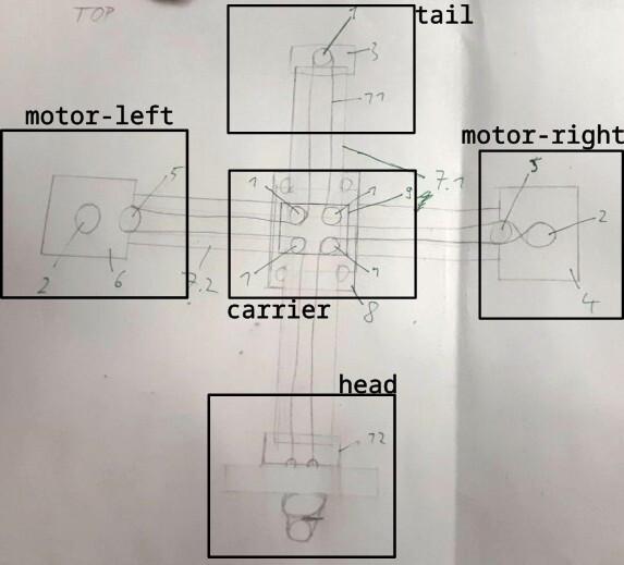
First, we met and thought about how to build the machine in general. We decided to use aluminum extrusions and wheels as linear guides. We made some initial sketches to better understand, how the machine whould look like and what parts we would need.
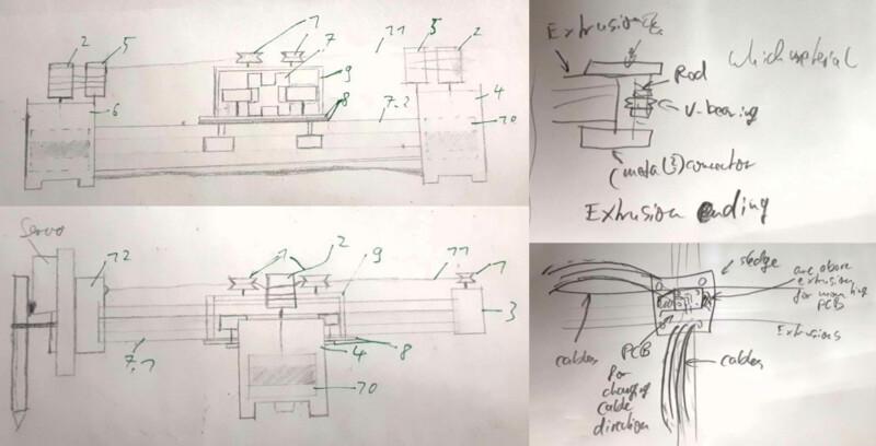
Here you can see the inital concept. The wheels for the linear guide as well as the v-wheels for guiding the rope are placed on the middle carriage and the rope is fixated at the head.
We split the work into the following sub tasks.
- Trying out RAMPS (a kit containing an Arduino for the firmware and drivers) and get it working with Printrun.
- Designing the parts for the tail
- Designing the motor mounts.
- Designing a head with a Pen holder and a mechanism to lift it.
- Producing and testing the prototypes and the parts needed.
Mechanism & Parts
Design
Our Instructor suggested the following workflow:
- Rapidly designing and and assembling a dummy prototype, either using cardboard or digitally, using Blender. The idea of this step is to have a rough sketch and to get an idea of the mechanism, dimensions, etc.
- Design every part (yes, every part) in a CAD software and assemble that exactly in the way we would assemble it later in reality. Following his experience, mistakes are mostly made with components that were not taken into account in the digital model previously.
- Iteratively fabricating the machine.
Due to us having less to no experience in machine building, we did not make to follow step one properly. Looking back, however, the sketch-making session at the beginning of the week helped us a lot with understanding what we want to do.
Our machine would consist of both standard parts (e.g. the aluminum extrusions, screws and bearings) and parts designed by us. The standard parts, we downloaded from various resources, such as GrabCAD and OpenBuilds. Most of the parts were retrieved by looking up another machine that uses extrusions and wheels for the guide and downloading the parts from there. For screws, we used the fasteners workbench extension for FreeCAD.
The initial design we kept simple so we could produce them fast and test out the mechanism. We built a flat motor bracket for connecting the motor to the extrusion:
We printed the capstan and pulley from the UrumbotXY 2.0 as well as a simple head.
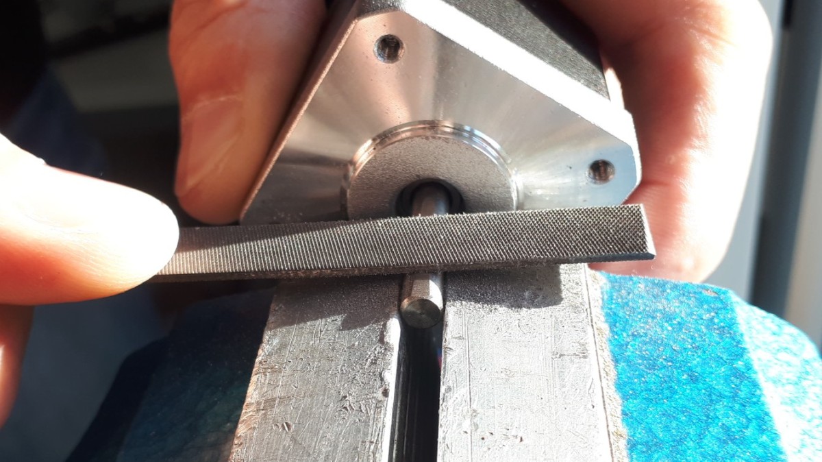
The motor axis we filed flat for the capstan to have a better grip.
The idea of the carriage was to have a plate and mount four wheels at its bottom and four wheels at its top to connect the horizontal and the vertical axis with each other. Additionally, we wanted to mount four v-wheels to guide the capstan thread. A plate for mounting the wheels we already had as a metal part. It was very sturdy, so we wanted to use it. However, it did not suffice to mount each of the wheels, so we designed a larger second plate to be mounted on top of the metal plate for mounting the other wheels.
A problem was that the wheels guiding the second axis and those guiding the top axis were mirrored in respect to each other, so the heads of the respective screws would have been very near to each other. Our instructor advised against that. We redesigned the carriage according to the feedback. It was at this time that we decided to use the eccentric screws to tighten the rope.
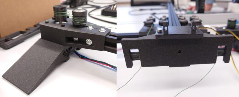
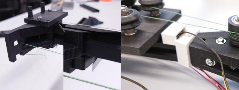
The tail was designed with one wheel. The wheel seen at the picture was substituted with a v-wheel later on.
Then we designed a new head with which we were able to fixate the capstan thread.
Apart from that we printed a cable chain we found at thingiverse to connect the head with the board. In the end we noticed, that the chain was not sturdy enough and that we could not use it for our machine. Due to time constraints we omitted it for this assignment.
Assembly & Manual Operation
Next, we assembled everything...
... cut threads, screwed everything down, assembled the capston drive rope...
... and operated it manually:
We were very happy that it worked because we were unsure about it and considered switching to a belt drive.
Re-Design
When we operated the mechanism, we needed to hold down the machine at its feet to prevent falling over. This was the first we improved.
First, just adding a little angle in the motor bracket as well as extending it to mount the motor in a more stable way reduced the oscillations, but did not avoid them completely.
Therefore, we added sideway stabilization as well. Furthermore, a mount for the end stop was added.
The improved head and the initial design for the pen mount can be seen below.
Besides the end stop at the foot, one also was added at the bottom of the head.
Also, a never-produced new cariage for mounting the cable chains to guide the cables from one of the feet to the head was designed.
Actuation & Automation
We now had a mechanism and motors driving it. The next step was to tell the motors what to do in order to draw a picture. This involed setting up a driver for the motor (a circuit that translates step signals into current flowing through the coils in the motor to make it move), a software that sends step signals to the drivers based on given machine code (referred to as firmware), a GUI that interfaces the user with the firmware, enable them to send machine code to the firmware and to come up with a workflow to generate G-code from an .svg file.
Setting up the Controller
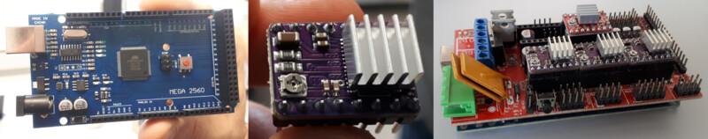
To automate the machine, we used a RAMPS kit. It is a set consisting of an Arduino board supposed to run the firmware, Pololu-style stepper motor drivers, as well as a shield for the Arduino board to connect power supply and drivers. The drivers we used were of the type DRV8428. For assembling everything, we followed the steps at the RepRap wiki.
The power supply we used had open contacts with above 200V.

We wanted to avoid touching them so a cover was designed using FreeCAD. Note the rounds where two straight pieces meet. This is to avoid the cover breaking at the corner.

Every driver had a slot to put it at. Under the driver there were jumpers. They could be set to configure microstepping. We set all jumpers to enable the setting with the smallest-possible steps. The driver carrier had an adjustable resistor which was used to adjust the maximum current the driver would provide to the motor.
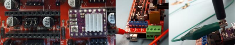 We followed this tutorial by Pololu. First, everything but the motor was connected. The maximum current was found from the data sheet of the motor. In our case it was 2.5A (we used a wantai stepper motor with the model number 42BYGHW811). Following the driver-specific information in Pololu's tutorial, the maximum voltage to be measured between the potentiometer and GND was 1.25V. We set the voltage to 1.2V to be safe that we do not give too much current to the motor. We repeated this procedure for two drivers in total since we had two stepper motors to drive.
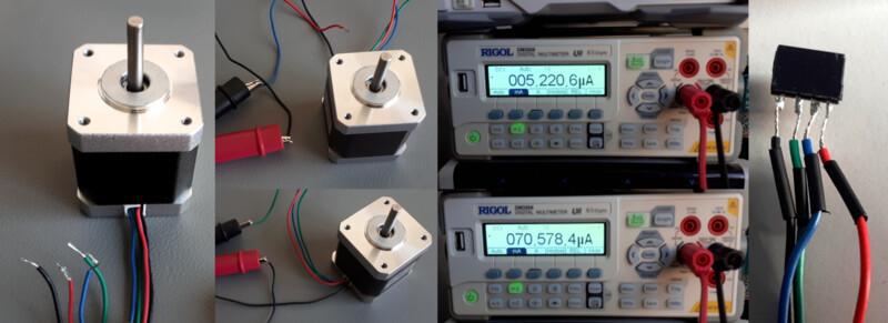
Afterwards, we needed to connect the motors to the board. Our stepper motors had four wires attached. The question to answer was how to arrange them so that the motor works correctly? Each motor contained two coils. The two ends of each coil were led out of the motor. There were two coils so there were four cables in total. To identify a coil pair, we measured the current between each pair of wires and turned the motor. This induced a current in both coils which could then be measured. The current induced was alternating current since the motor was turned manually. We measured with the direct current setting. This did not matter that much, because we only were interested if there is current flowing or not. We noticed a significant change in the measured current when the motor was turned. The pairs identified were blue, red and black, green.
 We soldered the cables so that the corresponding cables were next to each other. The next question was: does the motor turn the right way around? The direction of the motor could be changed without changing the firmware by just switching the cables. The following rules hold where
 1A 1B 2A 2B is the original order of the cables:
- If you change the order of one of the cable pairs (
1A 1B 2B 2A), the direction of the motor changes. - If you change the order of both of the pairs (
1B 1A 1B 1A), this is invariant to the direction of the motor direction. - If you change both cable directions and you switch the pairs (
2B 2A 1B 1A), this changes the direction of the motor.
It is important to note that one always needs to turn off the power when messing with the connections of the ramps board. Plugging the motor cables while there is still a power supply connected could destroy the circuitry in the RAMPS kit. For the following video the hello world sketch provided at the RAMPS wiki page was flashed.
Regarding orientation of the connector: the side of the connector that is facing the driver is labelled with "d".
Setting up Firmware & GUI
As a firmware to flash onto the Arduino we used Marlin. We followed the installation instructions and used PlatformIO. There were no difficulties with that. First, we flashed it without further modifications. Later, we adjusted the file Configuration.h to configure the firmware. To send machine code from a desktop PC/laptop to the firmware via USB, we used Printrun with Pronterface as a GUI.
Note that the baud rate needs to be the same in the configuration file of the firmware as well as in Printrun.
#define BAUDRATE 250000
After adjusting this, one needed to connect to the Arduino board by hitting the corresponding button.
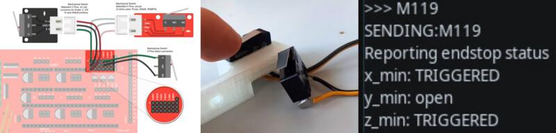
End Stops
We then connected the end stops to the ramps shield as described in the RAMPS wiki. With Marlin, the G-code M119 yielded the state of the end stops which was helpful for checking if their activation is recognized.
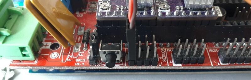
Servo Motors
To set up servo motors with RAMPS and Marlin one connects the servo motor as depcted in the RAMPS wiki. In Marlin's configuration, the following line needs to be uncommented.
#define NUM_SERVOS 1 // Note: Servo index starts with 0 for M280-M282 commands
Then, the servo could be controlled using the G-codes M280, M281, and M282.
Configuring Firmware: Motion System & Steps/mm
Our motion system was not as simple as "one motor turns, the other not -> only one axis moves", because instead of a cartesian motion system we had an H-bot. When both motors were turning in the opposite direction, the vertical axis was moving. When both motors were turning in the same direction, the horizontal axis was moving. When only one motor was moving and the other one not, both the vertical and the horizontal axis were moving to the same extent. For the mechanism to be automated correctly, we needed to configure the firmware accordingly. The configuration for the motor behavior was the same as with the CoreXY motion system, so we configured the firmware to drive the motors according to CoreXY's rules.
// Enable one of the options below for CoreXY, CoreXZ, or CoreYZ kinematics,
// either in the usual order or reversed
#define COREXY
//#define CoreXZ
//#define COREYZ
//#define COREYX
//#define COREZX
//#define COREZY
We put a tape onto our capstan thread and marked the extrusion with white tape where the right end of the tape attached to the thread was. We then moved 10mm in one axis, marked the extrusion again and measured the distance.
The distance traveled was 78.4mm instead of 100mm. We stated a ratio equation:
desired distance travelled/actual distance travelled = desired steps/actual steps. The unknown variable was desired steps. Resolving the equation yielded desired steps = desired distance travelled/real distance travelled * actual steps. The actual steps were taken from the original configuration which were 80. Calculating the new steps/mm yielded a value of 102 steps/mm. It is a good idea to repeat this procedure iteratively several times to get a more precise value for the steps/mm. However, already at the second iteration, we got a new value of 102.4 steps/mm, so we did not change the steps/mm any further. For more calculations regarding stepper motors in CNC machines, this calculator might come in handy.
/**
 * Default Axis Steps Per Unit (linear=steps/mm, rotational=steps/deg)
 * Override with M92
 * X, Y, Z [, I [, J {, K...]]], E0 [, E1[, E2...]]
 */
#define DEFAULT_AXIS_STEPS_PER_UNIT { 102, 102, 400, 500 }
In the end, it was possible for our machine to move correctly.
Below one can see a homing procedure.
Generating a Toolpath Using Inkscape
The machine code was calculated using the corresponding extension in Inkscape. The procedure can be seen below.
This made it possible for the machine to move according to the specified shape.
Drawing a Circle
For testing, we generated a toolpath to draw a simple circle. Checking the G-code using ncviewer confirmed that the G-code indeed described a circle being drawn.
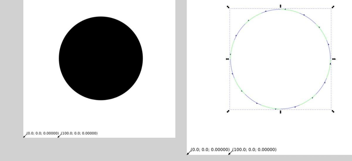
Unfortunately, the result was not a circle. Also, the origin of the start and the end position of the head was different. This was not as intended.
The problem here was thet the capstan drive thread was a little bit too loose and the pen was not stiff enough. We tightened the thread and, due to lack of time for this week, we used hot glue to fixture the pen at the machine's head.
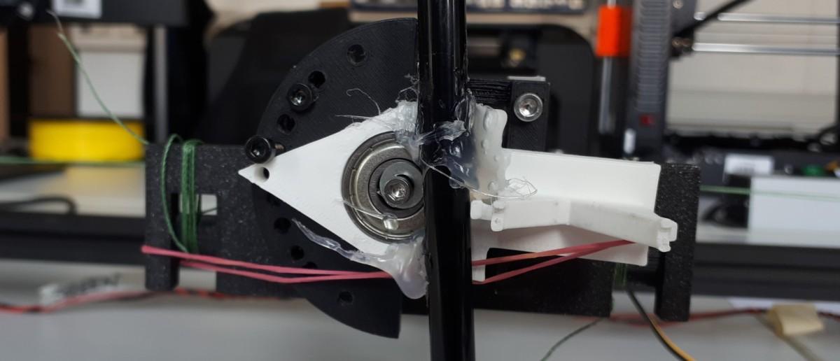
After that, a circle was drawn. This time, we also fixtured the paper by applying 3m77 spray onto the surface the paper was drawn on. When doing that we learned a trick: after using a spray can, turn it upside down and spray until only air comes out. This way, the nozzle gets cleaned. Otherwise it might get sealed by residual material from inside the can.
Working with G-code
During working with the machine and debugging it, we used G-code to manually control the machine. The following G-codes turned out to be used often:
- G092: set WCS position (useful for homing manually)
- M114: get position
- G054 - G059: handle different WCSs
- G91: relative coordinate mode
- G90: absolute coordinate mode
References
Below, some references are listed.
Urumbu Drivers
- Urumbu
- Urumbu, further work
- Project Sampo, using Urumbu
- OSAP, a web framework for talking with USB-driven hardware modules (e.g. motors), showing everything you would make on pcbs onto the desktop for rapid prototyping. However, this would be overkill for our project.
- Urumbu_IO
- UrumbubotXY 2.0
Capstan Drive
Other
- Cable carriers 3d printable
- flexible XY-stage
- Pen mount:
- http://www.makelangelo.com/
- https://wiki.opensourceecology.org/wiki/Ferdi
- motor
- cable carrier
- GrabCAD
Possible improvements
There were some points we could still improve with the machine.
- We have not been able to set up the servo motor for lifting the pen. Therefore, we could only create drawings consisting of one continuous line. The pen-lifting automation could be added.
- Right now, the origin of the WCS is at the top right of the machine's bed. It could be changed to be at the bottom l
- The capstan guide could be improved. Either the thread is guided inside the extrusion (for that one would need to design custom v-wheels) or the tail is designed wider so that the thread leading towards the tail is not angled.
- An enclosure for the power supply and the RAMPS board could be designed.
Digital Files
- All digital files can be found in this repository, where this commit is guaranteed to be the state of this documentation.
No comments to display
No comments to display