dr4wbck
The Idea
InitialyInitially, our Idea was to build the AxiDraw, but with a Capstan-Capstan Drive and inwith Core-XYan styleH-bot motion system to not need to have a typical belt and only need a rope or fishing line (and we wanted to try out this cool new technictechnique :D).
For this, we took bigmuch inspiration from the UrumbotXY 2.0 and first tried to imagine, how we would need to align the bearings to get the desired movement.
We made some initial sketches to better understand, how the machine whould look like and what parts we needed.
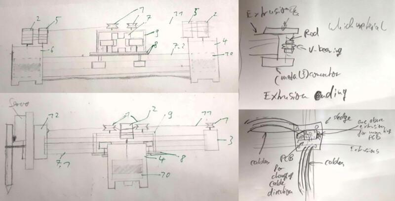
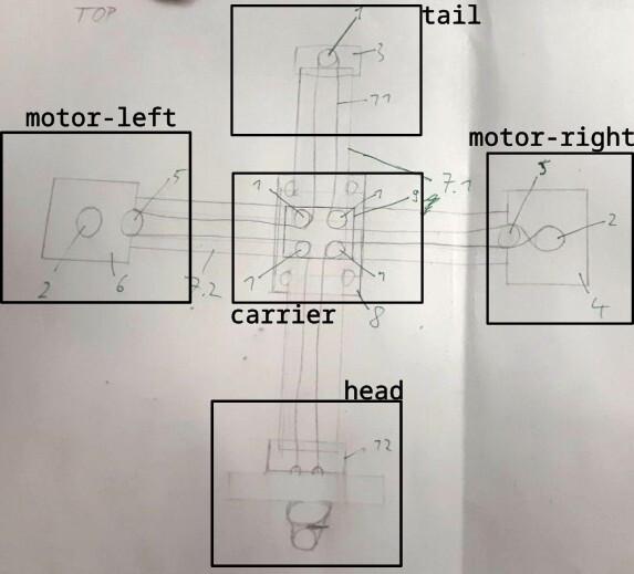
Then we seperated the machine in different parts that needed to be designed and to be done. Also here you can see the inital concept, which was that the corner-bearings are placed on the middle carrier and the rope is fixed on the head. (and also here we planed to place the carrier bearings over the second axis)
We where a bit overwhelmed of all the tasks that needed to be done and first needed to get into managing the tasks and distribute the tasks in the team. So we split the work into thouse sub-tasks
- try out and get the RAMPS working with Printrun
- design the different parts of the x and y machine axis
- design a head for the pen with z axis
- produce and test the prototypes and needed parts
Initial Design
In the initial design, we kept the design simple so we could produce them fast and test out the mechanism.
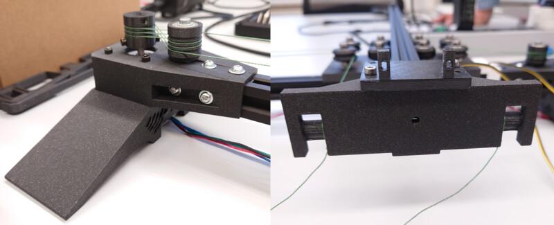
So we build a simple motor bracket for the motor and the linear rails:
Then we produced the capstan and pulley from the UrumbotXY 2.0:
An Initial head for:
Then for the carriage we had a Metall Carriage already as a part, which was very sturdy.
Here we needed to be carefull with the screws.
But the wheels for the second axis where on top of the other wheels, which we couldn't implement and Ferdi advised against it.
The tail was designed with only one wheel, which may have bin one cause for our problem.
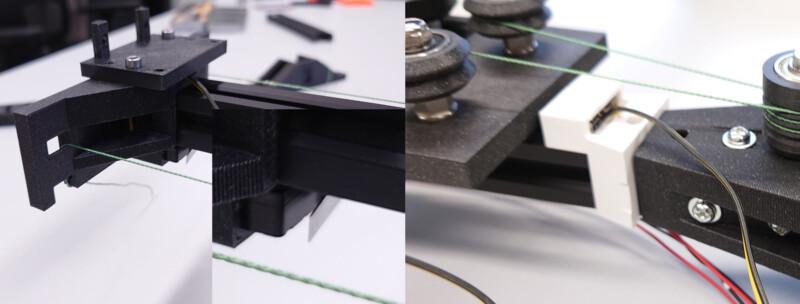
Then we redesigned it to use both metall carriage, which was pretty sturdy. Also we used eccentric screws to tighten the rope.
Then we designed a head for initialy screw down and tighten the rope.
Also we produced a wire chain to connect the head with the board. In the end we noticed, that the chain was not that sturdy and was not that usable for our machine -.-.
First Assembly
After designing and printing, we assambled everything...
... cut threads, screwed everything down, assambled the capston drive rope...
... and tried to operate it manually:
yay :D
And it worked nicely :P
Continuation & Redesign
When operating manually, we needed to hold it down so that it is stable, which was the first thing we improved.
First just making a little angle in the motor bracket improved it a lot but still was oscillating...
... so we created a sideway stabilisation, which then was pretty stable.
Here the head and the initial design for lifting holding and adjusting the pen.
Then we inkluded in the head and on the side an endstop for executing g-code.
And also a never produced new cariage for mounting the cable chains for the head.
Lessons Learned
- distributing the work in a team is hard
- also finding parts, that can be operated on parallel is not that easy
- nothings works out as expected and things that can go wrong, will go wrong (as told so before)
- we should have partitioned our time more efficiently, then we whould have had a good working product on time and not spend time on little, not necessary things
Setting up the Firmware
Getting it Running
#define BAUDRATE 250000
Determine Steps per Millimeter
// Enable one of the options below for CoreXY, CoreXZ, or CoreYZ kinematics,
// either in the usual order or reversed
#define COREXY
//#define CoreXZ
//#define COREYZ
//#define COREYX
//#define COREZX
//#define COREZY
/**
 * Default Axis Steps Per Unit (linear=steps/mm, rotational=steps/deg)
 * Override with M92
 * X, Y, Z [, I [, J {, K...]]], E0 [, E1[, E2...]]
 */
#define DEFAULT_AXIS_STEPS_PER_UNIT { 102, 102, 400, 500 }