CNC mill JarBeRi
CNC Mill by Jarni, Benedik, Richard
Checklist:
print finish sled design for X and Y Axis Goal for the day:
test firmware move motors with firmware design end stops Goal for the day:
Workflow:
Links:
https://cloud.tu-ilmenau.de/apps/files/files/104312242?dir=/Benutzer/CNC%20JarBeRi
3D modeling:
- Everyone is working on their subassemblies.
- Work in private directories
- Upload versions to the shared folder
Design decisions:
General
Standart PCB Sizes:
- metric: 150mm*100mm
- imperial: 127,38mm*102mm (5inch * 4inch)
Material Goals:
- PCB milling very precise
- 0,4mm traces
- Engrave stone
- soft limestone
Work Table (fixed)
- 160mm*120mm
- 15mm? height
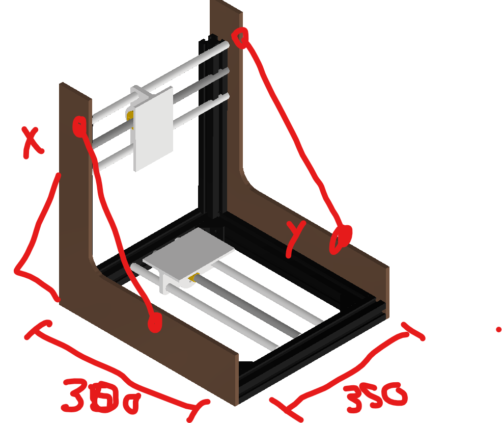
Outer Dimensions: (might change based on final design)
- 350mm width
- 300mm depth
- ? height
Assembly Groups:
Mechanical:
Y-Axis: (Jarni)
- leadscrew: trapezoidal thread T8
- two T8 nuts countered for minimal backlash
- new stepper + axle coupling
- preferred: prusa stepper axle assembly
- bushing for trapezoidal axle
- guiding rods
- 8mm
- linear bearings
- sled
- 3d printed part, maybe milled aluminium
- support structure for lower bed
- interface plate
- holes for T-Slot nuts
- friction fit for guiding rods
X-Axis: (Benedikt)
- leadscrew: trapezoidal thread T8
- two T8 nuts countered for minimal backlash
- new stepper + axle coupling
- preferred: prusa stepper axle assembly
- bushing for trapezoidal axle
- guiding rods
- 8mm
- linear bearings
- sled
- 3d printed part
- connected to z-axis
- interface plate
- holes for T-Slot nuts
- friction fit for guiding rods
Z-Axis:
- manual adjustment with screws
- flexure mechanism
Machine Bed (work table):
- upper bed: (waste board)
- HDF/MDF
- screw holes for fixturing?
- lower bed: steel or aluminium
- connect upper bed and lower bed with screws
Spindle and Spindle Mount:
- which BLDC motor?
- brushed motor from Ferdi
- BLDC motor
- treaded inserts for the mount
- spindle collet
- high strength ABS 3d print
- mill out of aluminium
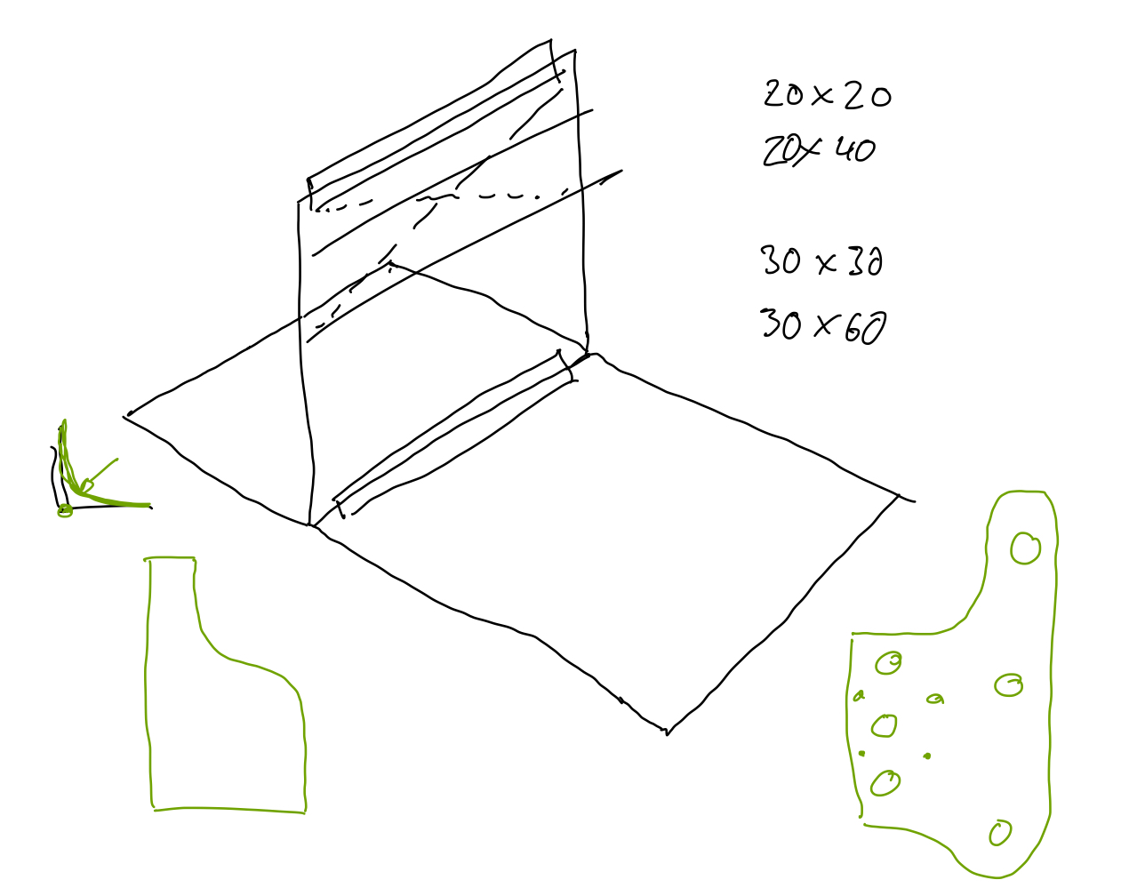
Frame:
- use existing: ITEM Profile 6 30mmx30mm (0.0.419.06)
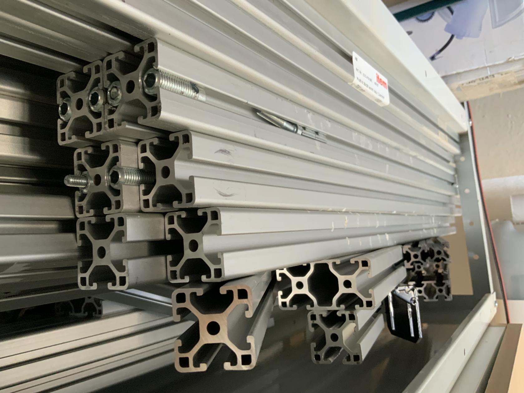
- vertical: 60*30 extrusion
- horizontal: 30*30 extrusion
- additional support by steel wires for structural rigidity
- T-Nuts

Electric:
- human interface
- housing
- display
- power
- lab bench powersupply
- cables
- Motors
- Stepper Motor
- plugs
- mechanical coupling
- Spindle Motor
- BLDC
- BLDC driver board
- Stepper Motor
- Endstops
- microswitches
Software:
- search for:
- Arduino mega software
- motor drivers libraries
- uns Fusion360 for 3D model -> nc code
Project Progress / Documentation:
First Idea to Sketch:
On Thursday, the day after the Mechanical Design and Machine Building lecture we decided to form groups in our local lab. It wasn't easy to form a group in the first place but after longer discussion we formed a group of three: Jarni, Benedikt and Richard.
We wanted to build a use full tool for our lab and get some redundancy for our existing CNC the Carvera Makera. Machines often have issues or have downtime due to maintenance thats why it is use full to have a backup if something goes wrong with the Carvera mill. For us building a X-Y-Z computer controlled coordinate system was a completely new topic, what made this project exiting in the first place. We took our existing machines in the lab as a reference and did some research online about homemade CNC's. We checked the following:
- Carvera Makera
- Prusa MK4s printers
- Pico V2 milling machine
- Ferdis existing knowledge on CNC's
We did our Idea sketches patially in CAD software (Autodesk Inventro) and partially in 2D sketching software (Goodnotes). 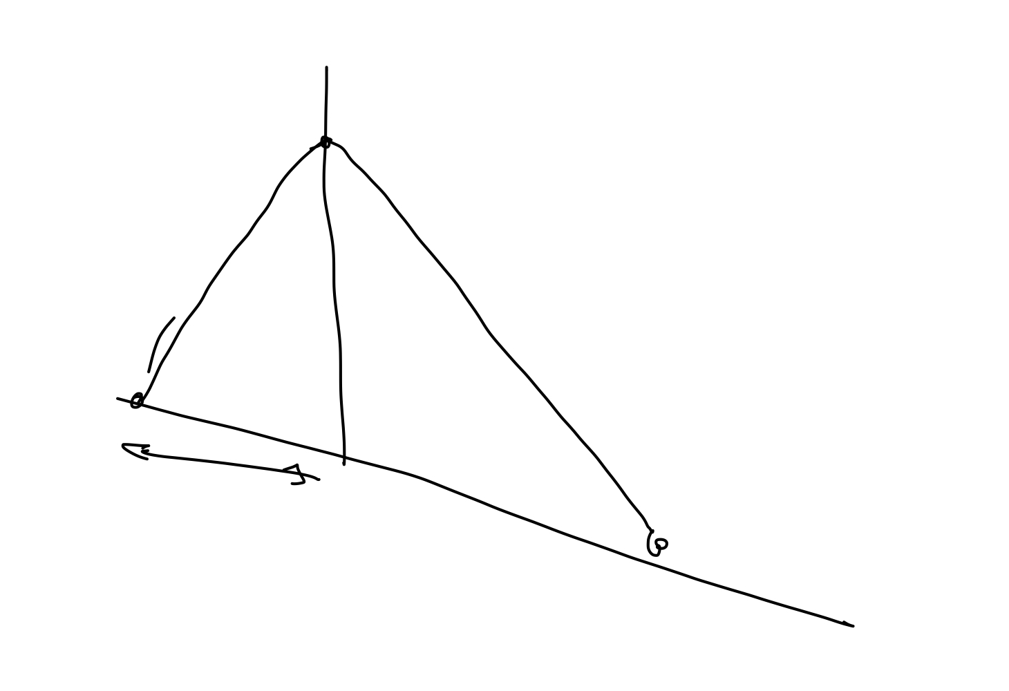
Idea Sketch to Mechanical design:
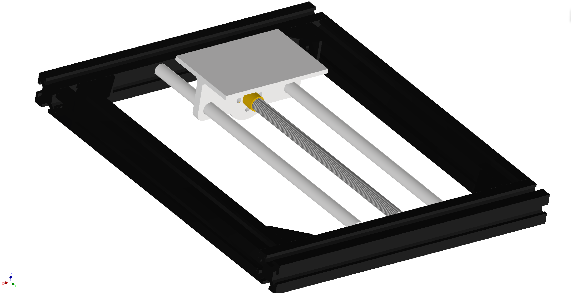
First Design:
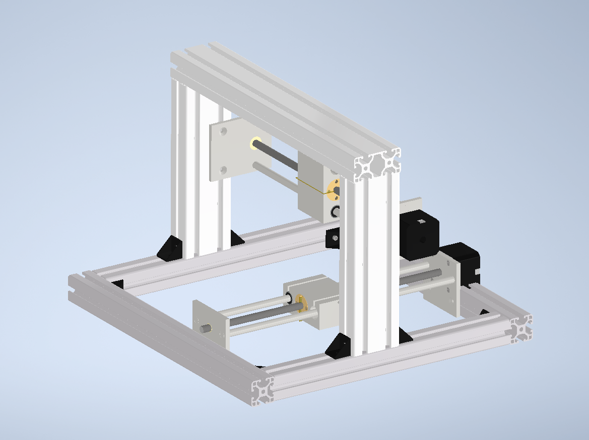
This is the first 3D Design Jarni and Benedikt made. It features already the main two Axis X and Y with the T8 screw nuts, sleds, rods and stepper motors. Now it was time to test some parts of the design with the 3D printer!
The test print showed some assembly issues we had If we wanted to use threaded inserts.
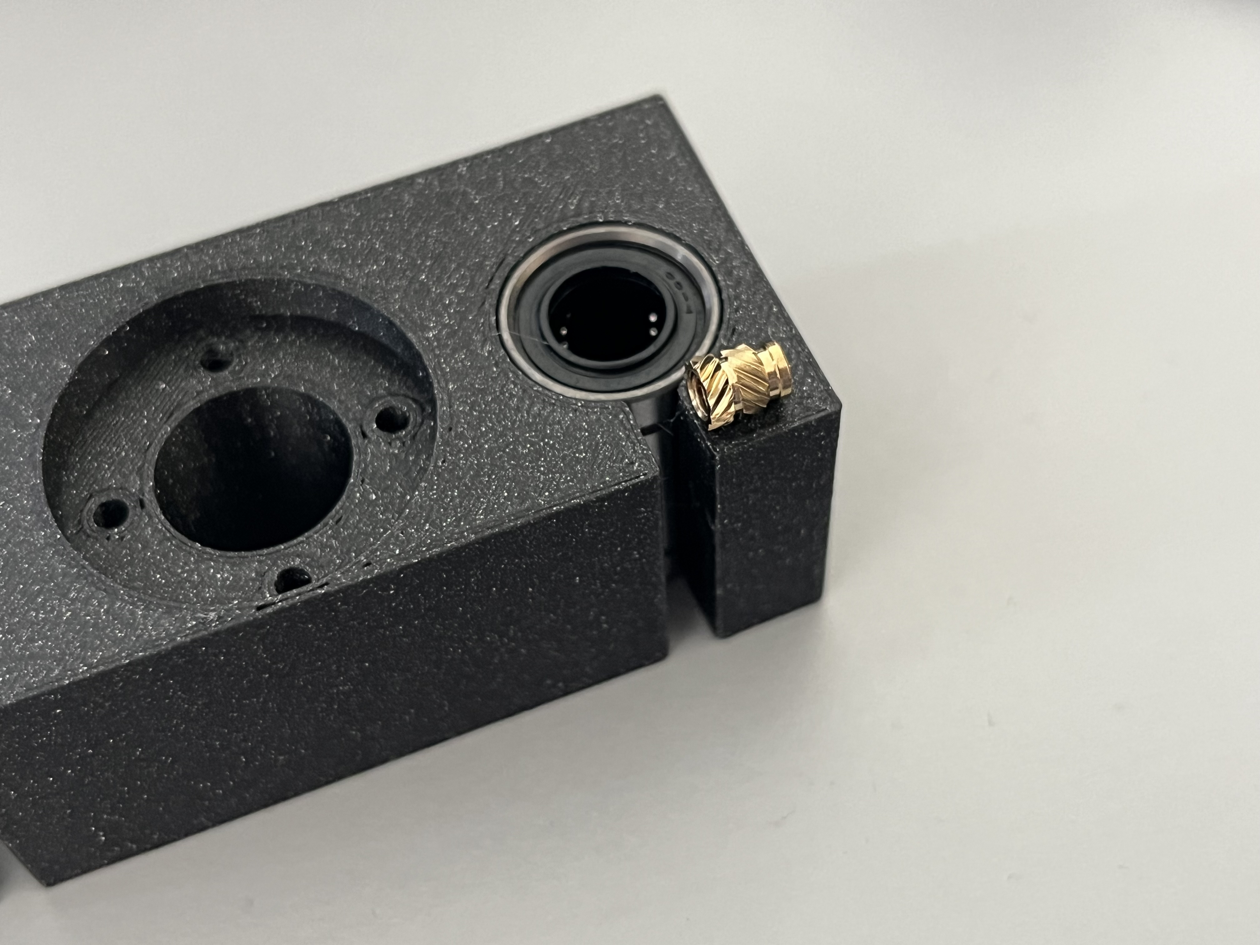 (V1)
(V1)In the second iteration Jarni added some more material and the ability to add threaded inserts.
-> instert picture here
(V2)
right screws for version V3: M3 20mm or 30mm
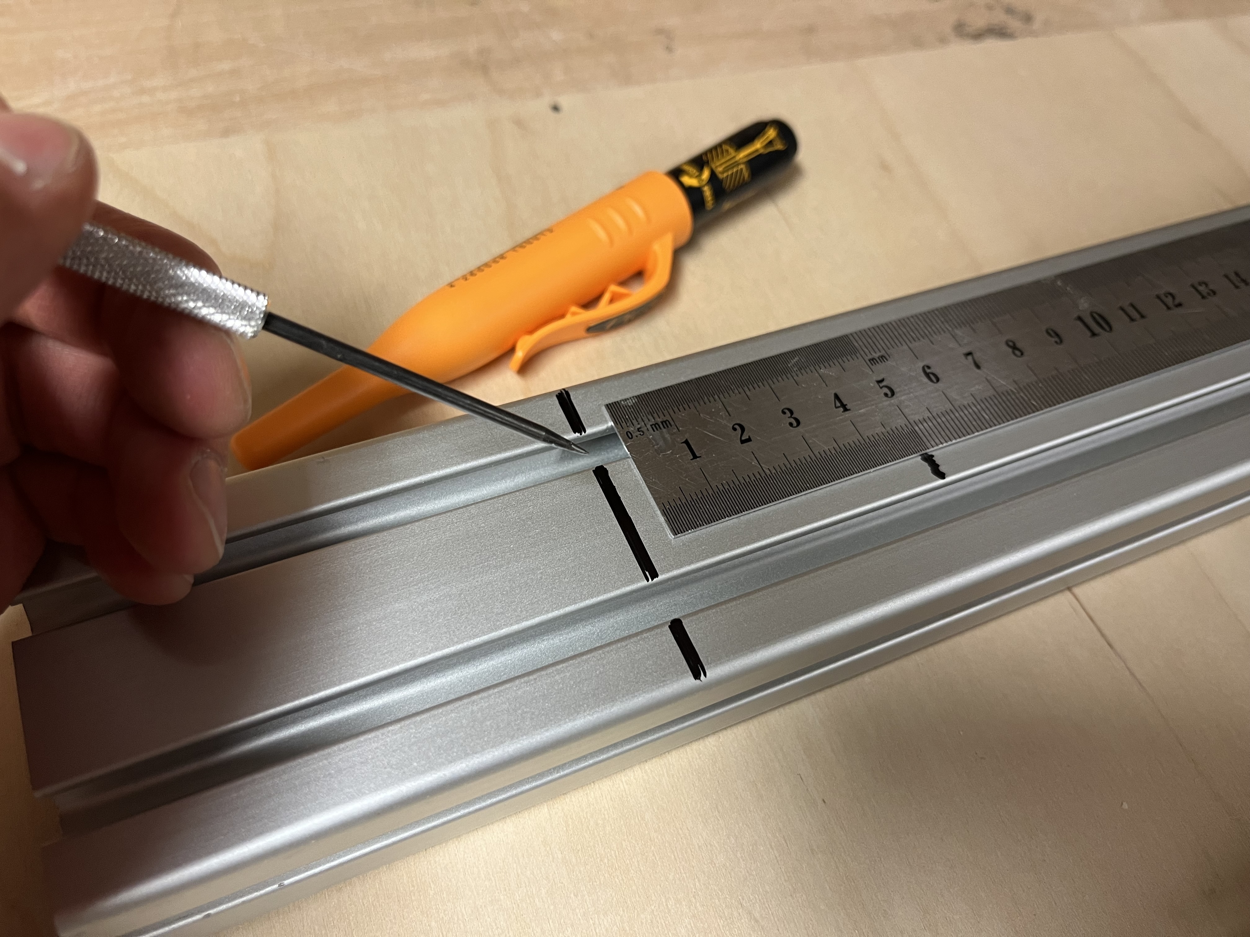
Cutting the Extrusion
- 30*30mm
- 2X 300mm
- 2X 360mm
- 30*60mm
- 2X 250mm (currently 200mm in cad design)
- 2X 360mm
M5Cutting 10mmthe extrusions did not turn out to be easy because they needed to be exact in length and right-angled. The tool we used for T-Slotcutting nutswas 24Xthe plunge saw with a blade for aluminium.
Y-Axis: (Jarni)
Electrical and Software Design:
For the electronic components we relied on the RapRep parts.
What ist RapRep? RepRap is humanity's first general-purpose self-replicating manufacturing machine.
RepRap is openSource software and hardware framework that has many derivitives and versions. For our project we used the standart RAMPS 1.4 board and a Arduino Mega.
RAMPS board
We used the official documentation of the RapRep
Functions we need:
- Endstops
Functions we do not need:
- Heatbed controll
- Hotend controll
Endstops
official Wiki RepRap - Endstops
RAMPS 1.4 offers no pull-up circuits, current limiting resistors or other protections.
Wiring improperly an endstop that uses 5V may damage an IO port on the ATmega 2560 or the Arduino itself, this is a particular issue with clones of the Arduino ATmega2560.
- put pull up and pull down resistors close to the board
In firmwares a setting is available to enable or disable built-in pull-ups, for example in Marlin you have the ENDSTOPPULLUPS constant in configuration.h, this option is enabled by default.
- different Endstop versions are available
- usually PCB mounted
Motors are a common source of noise. Keep endstop wiring away from motors or use strategies like twisted cables or or used screened cables to reduce the noise.
Stepper:
The stepper cables should not be disconnected from the boards while powered on.
- For A4988 setting all the jumpers will set the micro stepping to 1/16 of a step
- Turn down trim poti to zero, open up to 25% as a start value for the motor current.
Firmware:
- use Marlin Firmware
idea list:
component list: mechanical structural: - alu extrusion 20*20 moving: - 2x 8mm leadscrews with brass nuts - 4x 8mm guide rails - electrical: mechatronic: manufacturing methods:
- milling parts
Links:
-
https://marlinfw.org/