Trihedral Corner Reflector
The goal was to build trihedral corner reflectors to be used in a radar training accompanying the lecture "Fundamentals and Systems of Radar Technology" (FSRT). This lecture is offered by the "Radio Technologies for Automated and Connected Vehicles" research group.
New reflectors were required after the FSRT training has been modernized, financially supported by the examING project.
Analysis
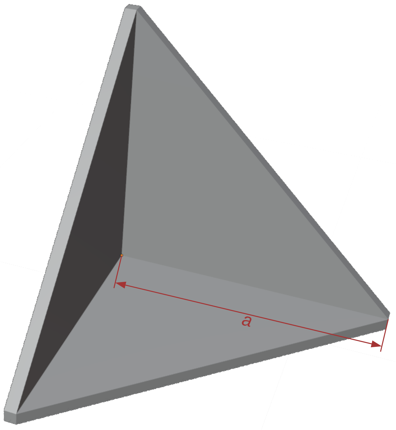
A trihedral corner reflector is basically made of three equal right-angled triangles. The first task was to define the length a of the legs (cathetus).
The reflector shall work in a frequency range of 77 GHz to 81 GHz. This corresponds to wave lengths of approximately 3.7 mm to 3.9 mm. Hence, any leg length a that is significantly larger than 3.9 mm is will be okay. However, the corner reflector shall still be handy and lightweight such that anyone can hold it easily.
If For the following analysis, we used the center frequency of f is= the79 frequency, andGHz.
Let c0 isdenote the speed of light (in vacuum),. Then, the free-space radar cross-section (RCS) σ can be computed as follows.
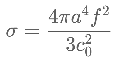
For more details, see here.
We chose a = 69 mm which results in an RCS σ ≈ 6.6 m² (6.5932... m²). We chose this value since the rounded RCS of 6.6 m² (rounded to one decimal place after the comma) would require a leg length of 69.017 mm, which is sufficiently close to an integer value (69 mm). Additionally, 69 mm is more than 10 times larger than the maximum wavelength of 3.9 mm.
Building
1. Building a jig
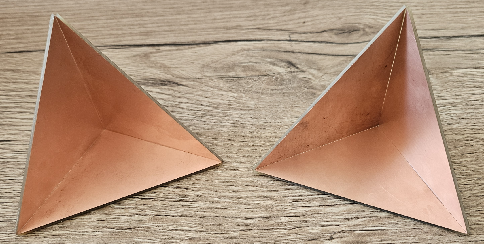
The final reflector is made of copper-coated plates that can be used to create PCBs. For each reflectorm, three right-angled triangles are have to be cut out and glued together. To make the gluing process easier, we first designed and 3d-printed a jig.
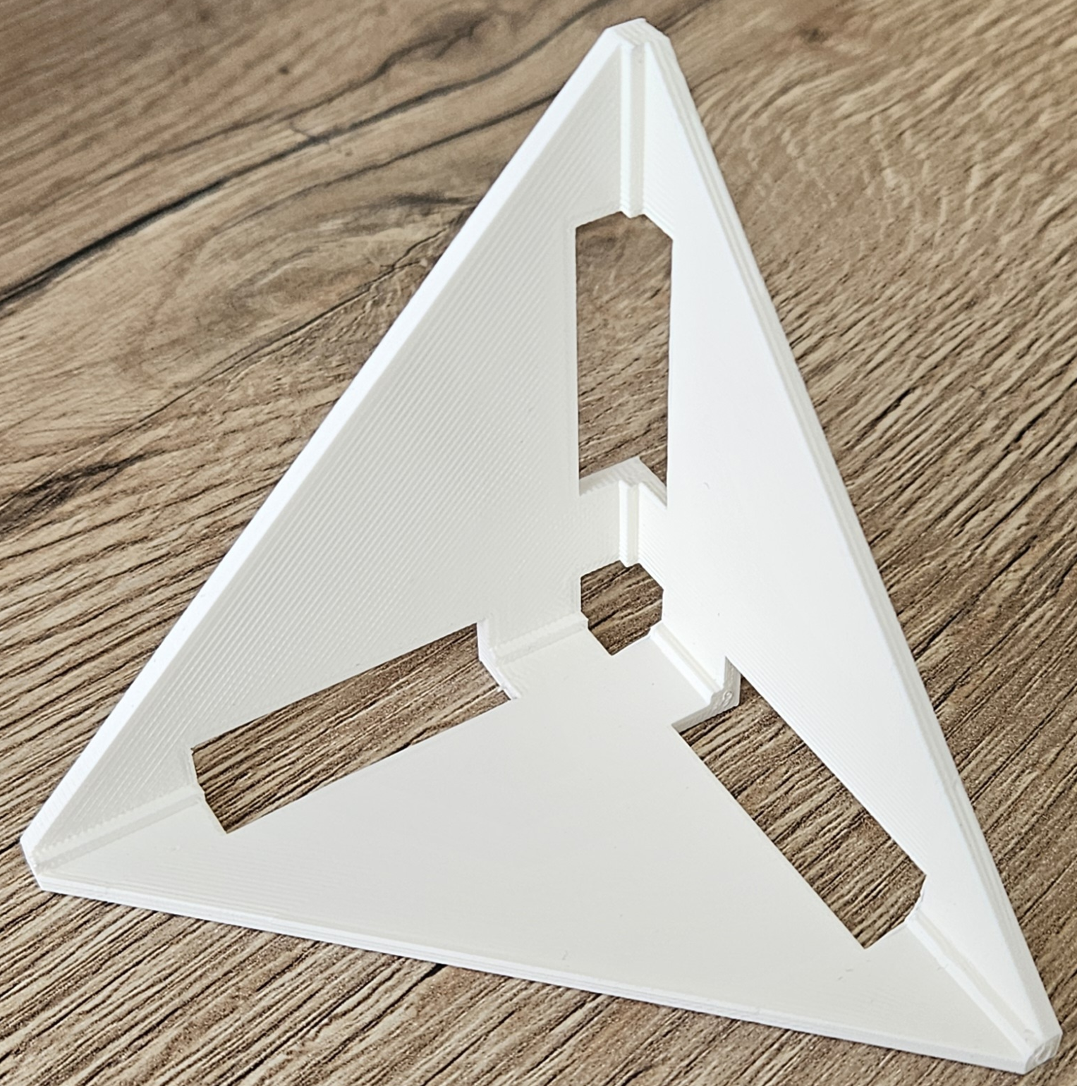
The jig has several cutouts. These are used to glue the triangles together. The jig is made for plates of 1.6 mm thickness. The FreeCAD files and STL files are attached to this page.
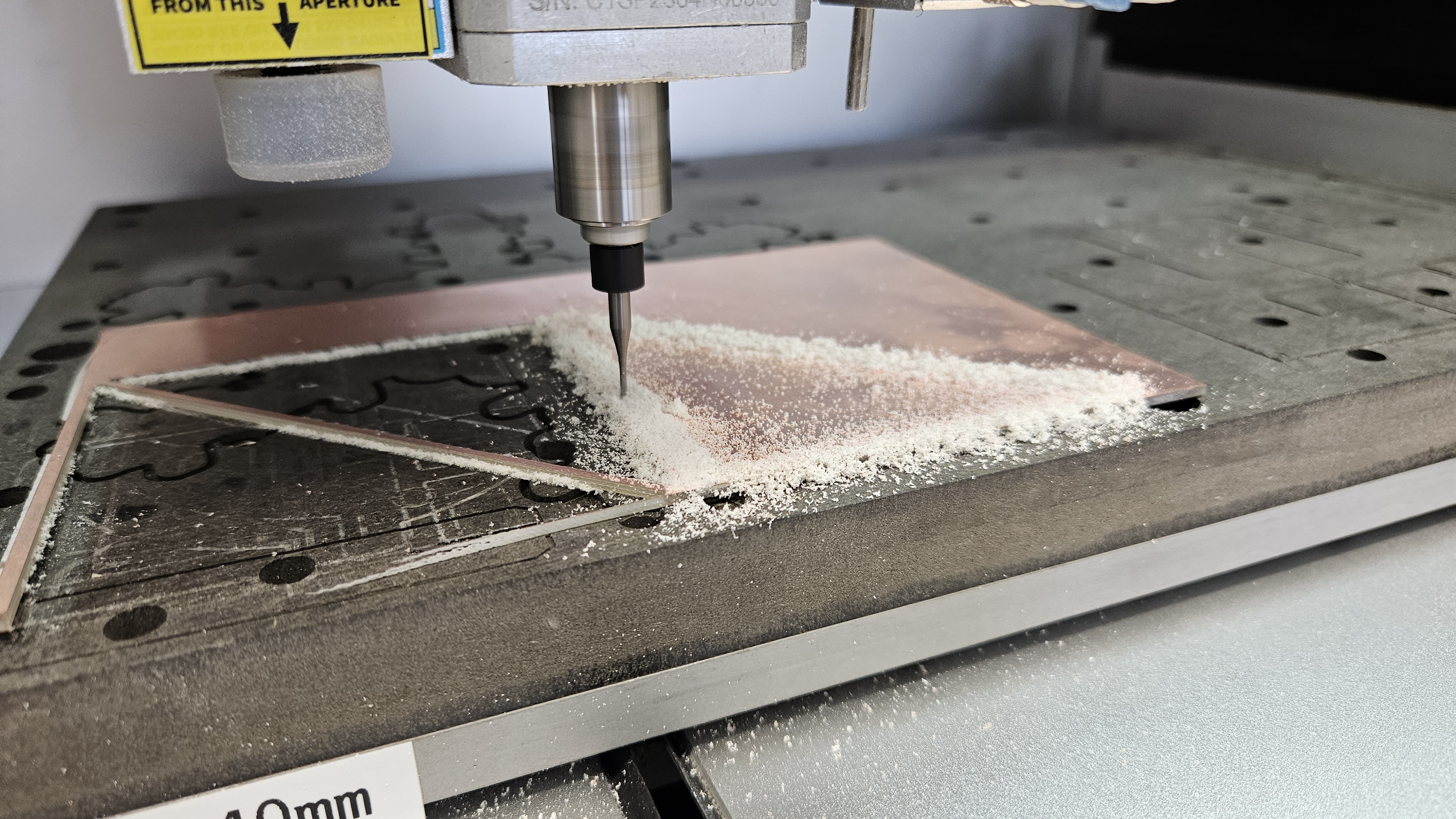
2. Cutting the triangles
The triangles where cut out using a CNC mill.
3. Gluing the triangles
The triangles are glued together by inserting them into the jig and fastening them using clothespins.
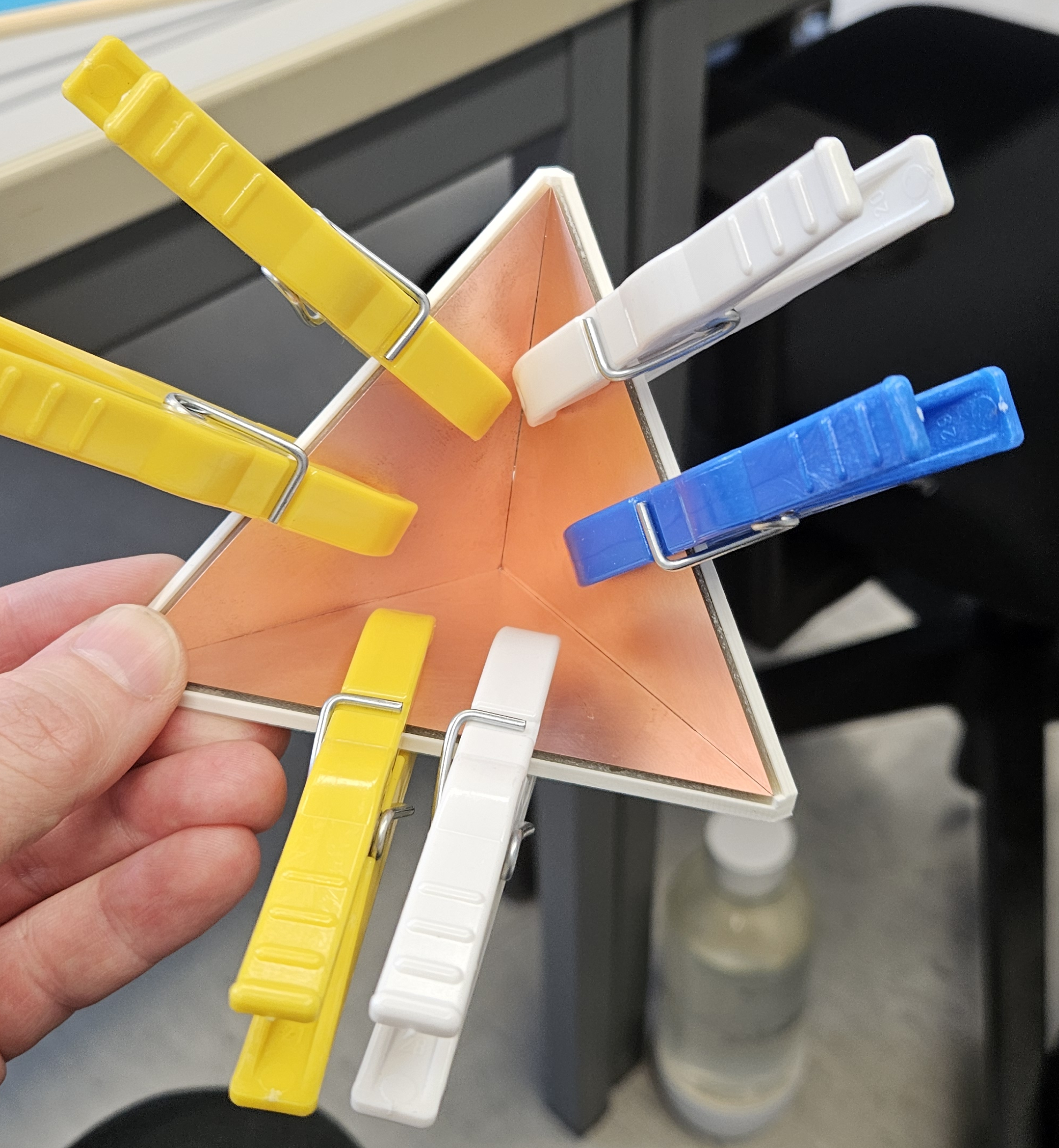
The glue is applied from the back through the holes. Once the glue is set, the clothespins can be removed.

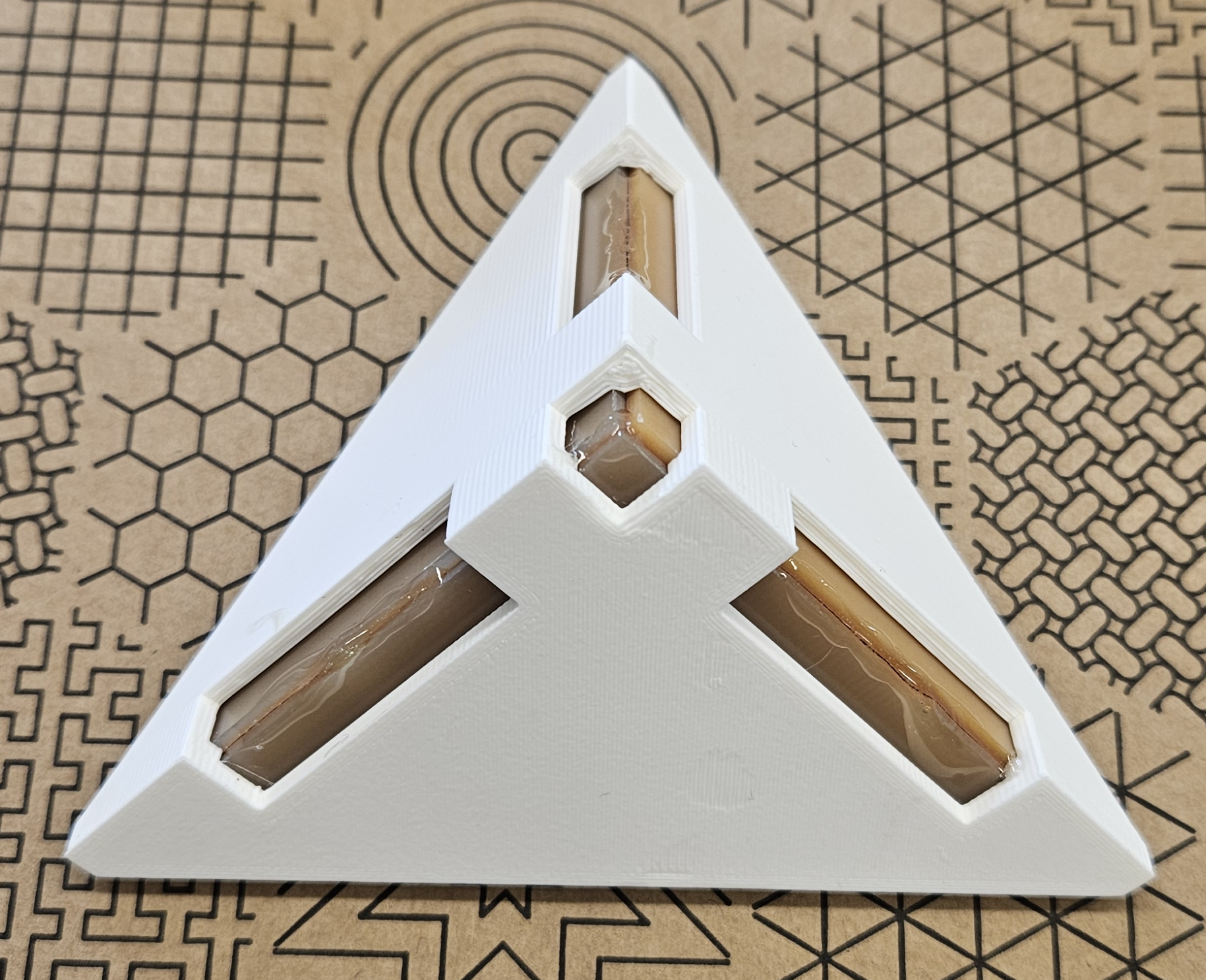
Anywhere the glue touches the jig, a knife with a sharp blade (e.g., a cutter knife) can be used to cut the reflector free from the jig. After that, some controlled force is required to push the reflector out of the jig. remaining glue can be removed from the jig using the knife.
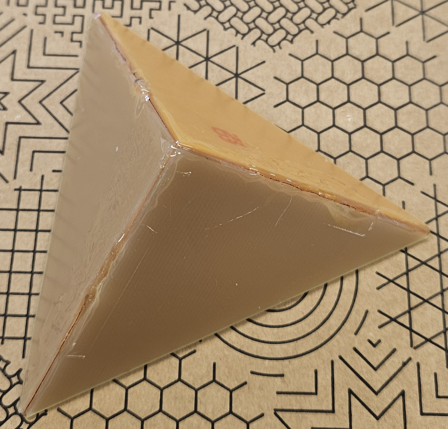
With the reflector out of the jig, the remaining parts of the edges (where the jig covered them) can be covered with glue. Let this dry.
Aftermath and findings
- The jig was indeed helpful when gluing the triangles.
- One could design an extra inner part for the jig, which holds the triangles more firmly than the clothespins.
- The glued reflectors still have small gaps between the triangles, since it is hard to get the edges of the triangles really tightly together.
- The glue is rather thick, which could make it hard to mount the reflector into some other object. Possibly, one could create a flat surfaces by cutting off the excess glue with a sharp knife.
- In order to create a more precise trihedral, it would be better to cut or to mill it directly from a single solid piece of metal or at least create a jig from metal.
<math xmlns="http://www.w3.org/1998/Math/MathML"> <mfrac> <msup> <mi>π</mi> <mn>2</mn> </msup> <mn>6</mn> </mfrac></math>