Machines
Available machines, infos and documentation for them.
- CNC Milling machine
- Specification/Available Tools
- Safety Instructions
- Carvera How to Use
- Tips and Tricks
- Maintenance
- Troubleshooting
- Lasercutter
- Vinylcutter
- 3D Printer
- French Cleat
CNC Milling machine
A small enclosed CNC Machine with a Tool changer mainly used for milling PCBs or small wood/metal things.
Usefull Links:
A bigger, non enclosed CNC Machine with a lesser stiffness for milling bigger materials.
Usefull Links:
Specification/Available Tools
Carvera Makera
Features
- Tool Changer (6 Tools)
- Auto-Z Probe
- Dust Collector (mainly for bigger chips)
-
- Axis for rotaty objects
Specs
- 36cm(X) * 24cm(Y) * 14cm(Z) Volume
- 9.2cm(Diameter) * 24cm(Length) 4. Axis
- 200 watt
- collet 1/8in integrated (optional: 1/4in, 6mm, 4mm)
- 600cm/min max X/Y Axis movement speed
- Less than 0.01mm Runout
- 0.01 mm motor precision
- 0 - 15000 RPM Spindel
- 0.8 liter Dust Tank Volume
Machinable Materials (e.g.)
Wood:
- Hardwoods
- softwoods
- MDF
- plywoods, etc.
Plastic:
- Foam
- PVC
- ABS
- Acrylic
- PC
- HDPE, etc.
Composite materials:
- Carbon fiber
- FR1, FR4, etc.
Non-Ferrous metals:
- Aluminum
- brass
- copper, etc.
Stepcraft D840
Features
- MDF machine table with aluminum T-slots
Specifications
- Working Space (X,Y,Z): 594 mm x 883 mm x 132 mm
- Clamping Surface (X,Y): 616 mm x 920 mm
- Ø 43 mm tool holder
Machinable Materials (e.g.)
Wood:
- softwood
- hardwood
- plywood
- artificial wood
Plastics:
- thermoplastics
- ABS
- PE
- PP
- soft/hard PVC
- Lexan®
- polyamide
- Plexiglas®
CFRP / carbon
Non-ferrous metals
Elastomers, duroplastics
Mixed materials
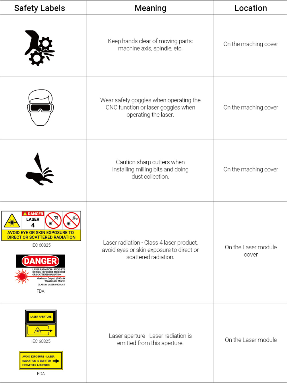
Safety Instructions
Our Recommendations
- when milling a material, keep the lid closed
- always think about z heights to not mill into the bed
- for PCBs and not milling through set it on top
- for anything else, set it on the
- do not wear headphones so you can heat, if something is not right in the milling process
- DO NOT LET THE MILL ALONE
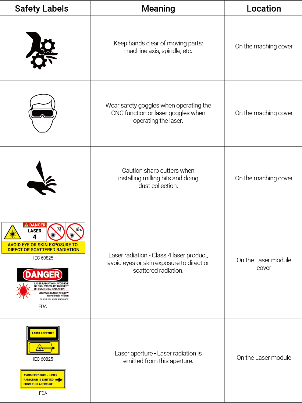
Makera Safety Instructions
-
Always wear safety goggles when operating Carvera, especially when the protective cover is open.
-
Always wear laser protection goggles when using laser function.
-
Please wear hearing protection when Carvera is machining on the hard materials.
-
Do not put your hands close to the spindle or machining area. Keep the protective cover closed when operating Carvera.
-
Do not leave your Carvera unattended while it is machining.
-
Please be aware of the sharpness of the milling bits during installation, dust collection, and other operations.
-
Milling and laser carving will generate heat. Inappropriate parameters will cause fire hazards. Make sure an extinguisher is in your vicinity.
-
Some materials are harmful to people when machining or laser craving, such as carbon fiber and epoxy resin. Please wear a face mask and turn on the automatic dust collection.
-
Do not expose this machine to rain or wet conditions.
-
Keep children and bystanders away while operating this machine. It requires supervision and the assistance of an adult when children use this machine.
 (Source)
Carvera How to Use
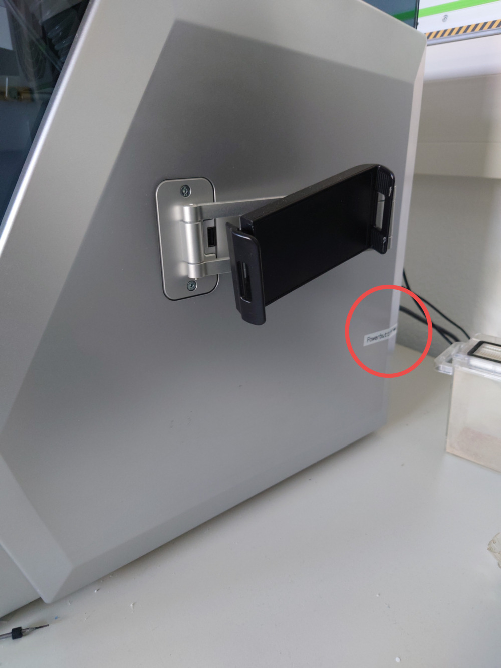
1. Turn On
- Use the Back-Switch to turn on the CNC:
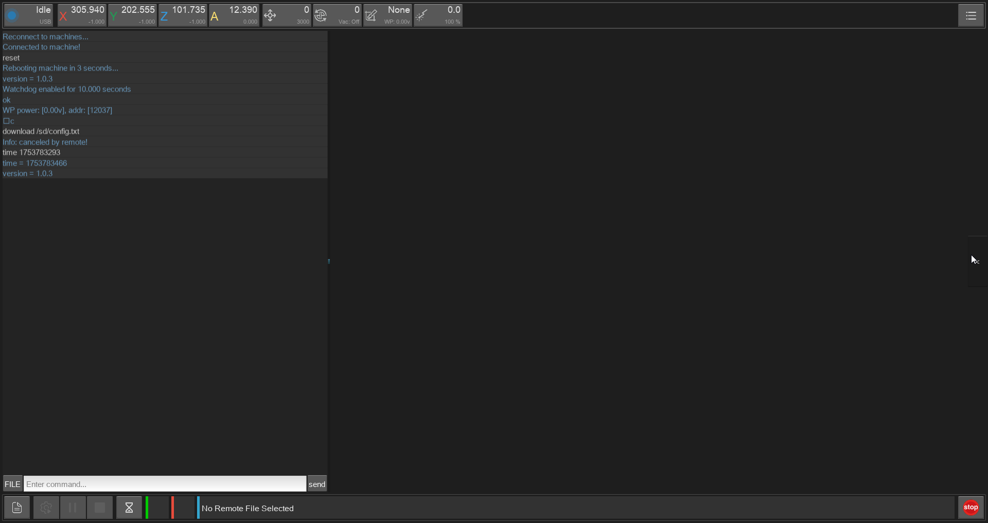
2. Connect and Home
You should always home the machine before milling, (even after starting it as a good practice)!
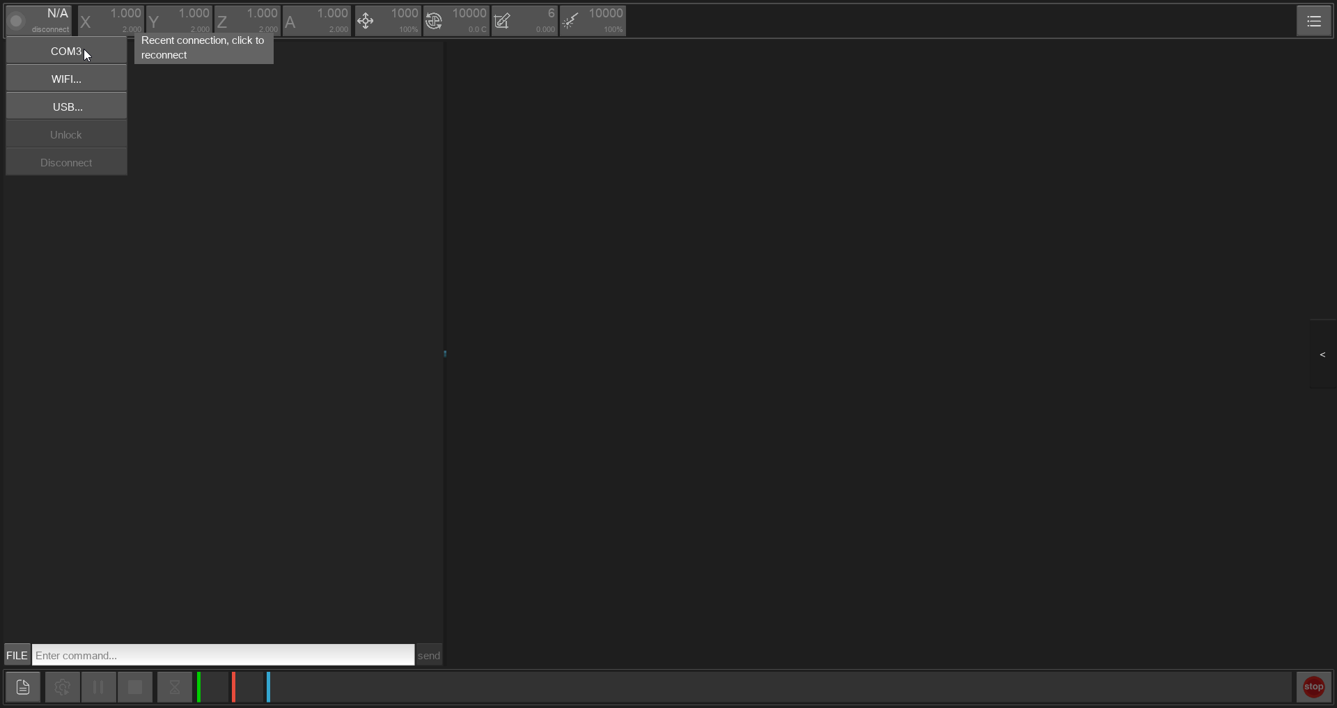
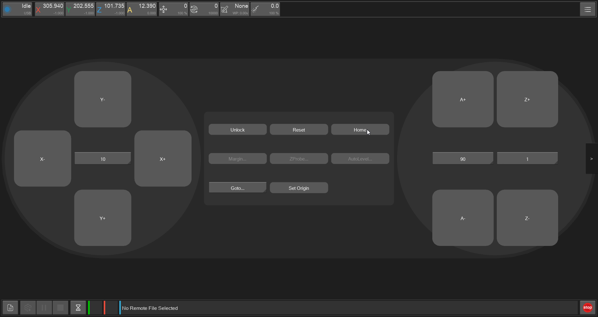
- To do that, open makera controller:

- Connect the software via USB on the top left corner:

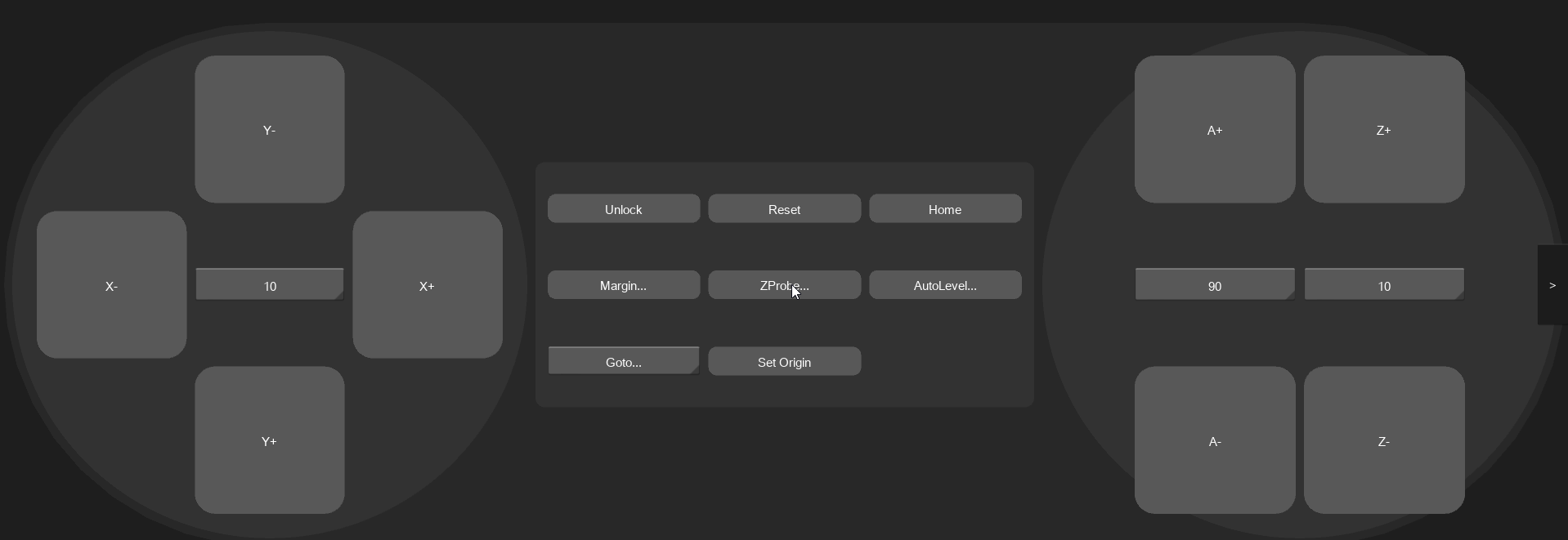
- Go to the side panel and press 'HOME':
| Side Panel Button on the right | Virtual Controller with 'HOME' in the middle |
|---|---|
 |
 |
3. Fasten the Workpiece
Then use the controller to move the bed thowards you and fasten your workpiece:
| Type of fastening | Example |
|---|---|
| Clamps Place the clamps on the bad and tighten the workpiece with them |
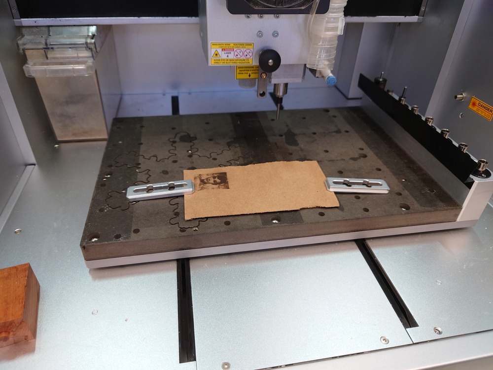  |
| Tape on a flat workpiece, place some tape on the bottom equally and just stick it onto the bed |
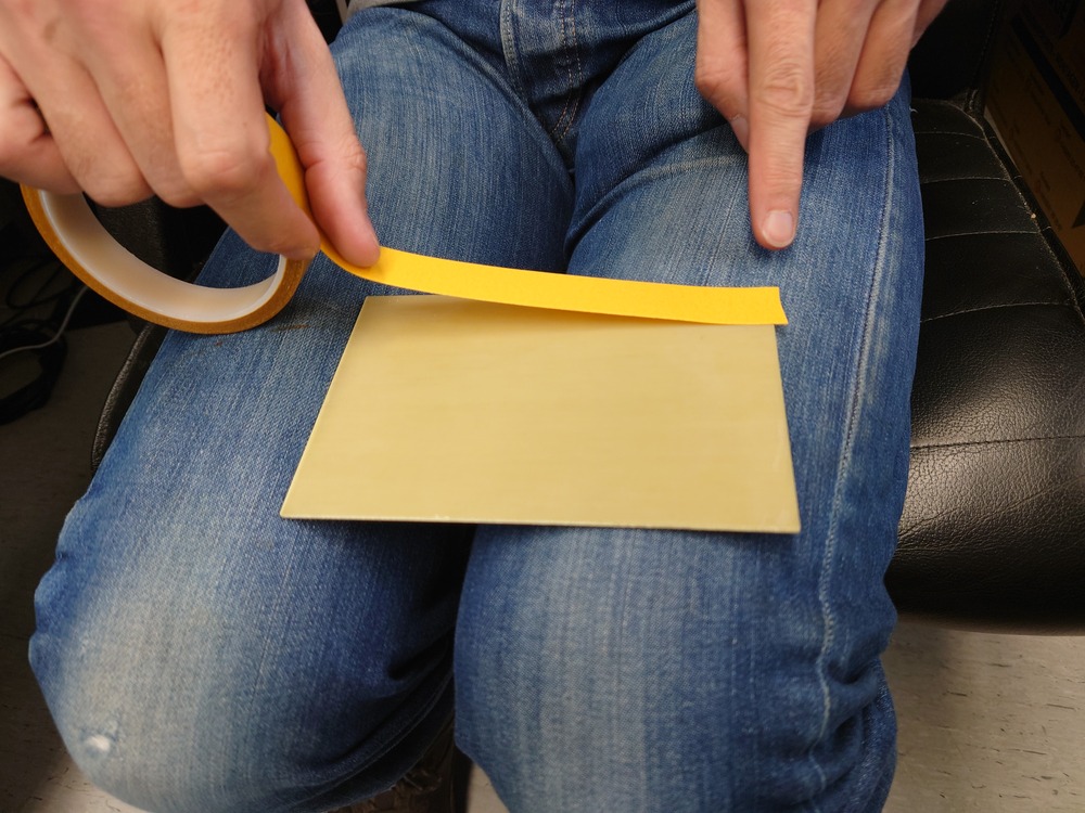 |
| Vacuum | TODO |
| Screws | TODO |
4. Zero
Then go to you work origin and use top left buttons to set it individually:
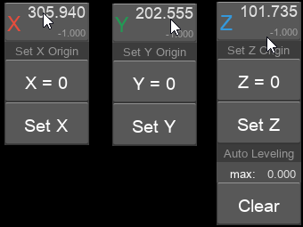
Or use the button 'Set Origin' in the controller on the right:
Auto Z Probe
Finding the Z-zero-point is more special because of the precision needed for it. For this, the Auto Z Probe can be used like this:
- Make sure, the Auto Z Probe is in the tool changer
- Place the tool where you want to measure the Zero Point
- Go to the controller and press 'ZProbe'

In this case we set the origin on the bottom of the workpiece.
Before Milling
It is also possible to probe before the milling (the Check-Box with 'Auto Z Probe'):
5. Upload & Start GCODE
First you need to upload a file to the machine, then select it and then, you can run it.
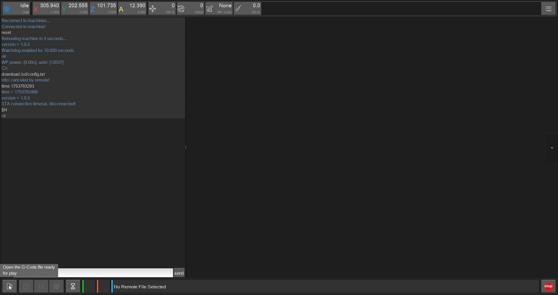
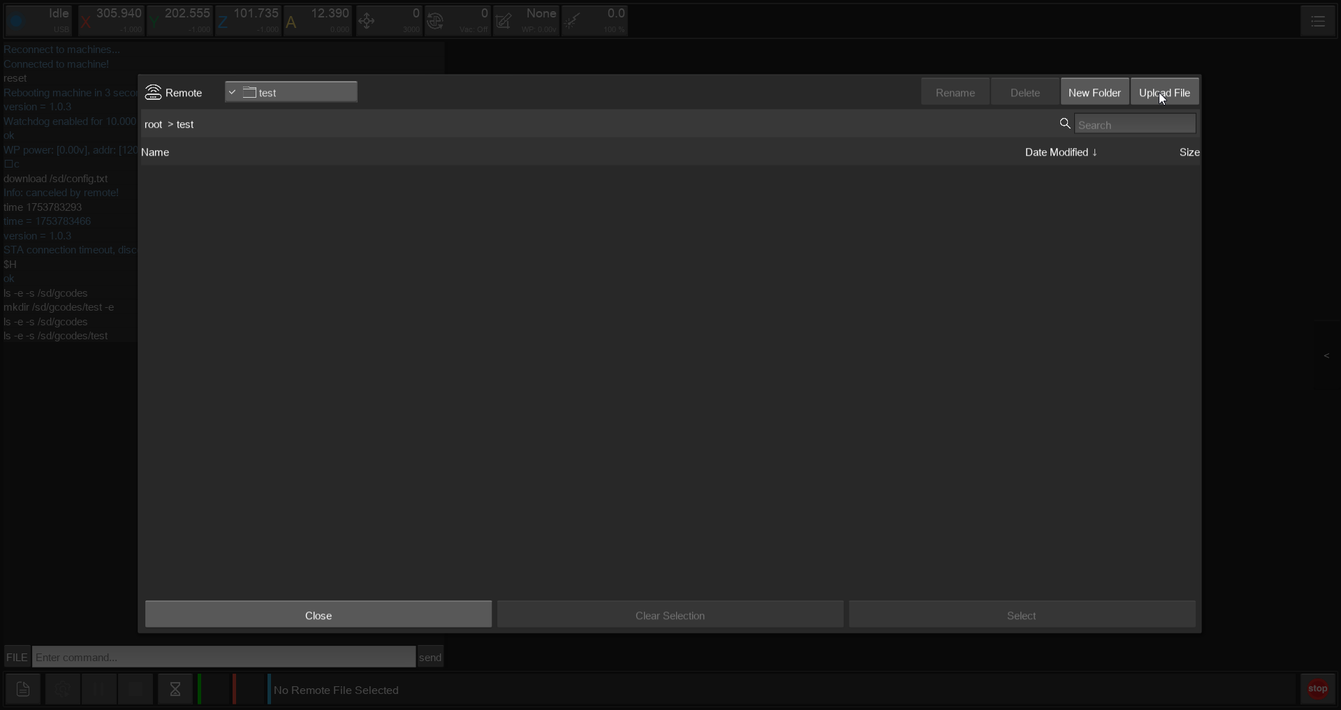
- Press the File-Icon on the bottom left (or in the top right hamburger-menu)
 Then the carvera file-manager popup appears.
 - Then go to your folder/ create a new one for you and go to the top right 'Upload File'

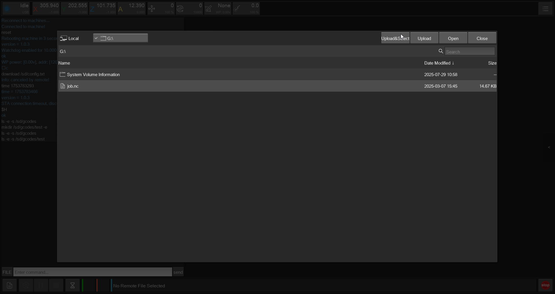
- Then use the top left to navigate to your file and then use 'Upload&Select' to load the file onto the machine and select it for milling.
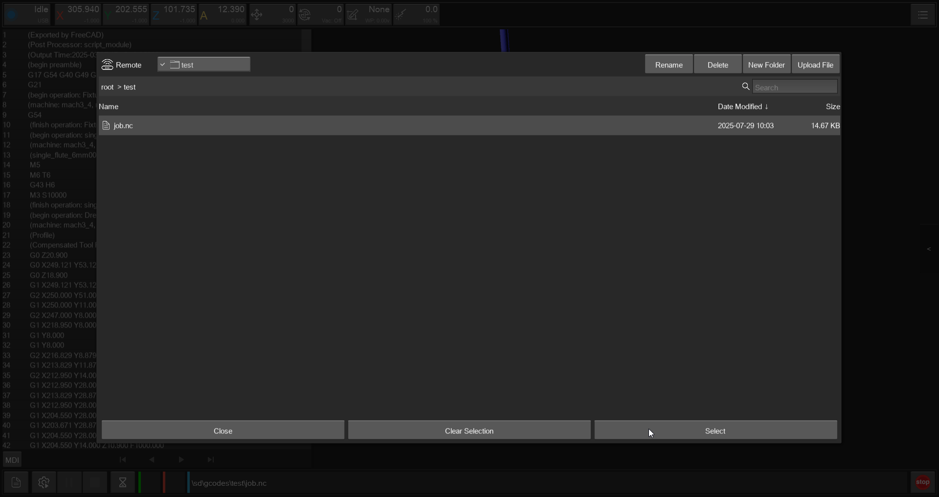
 Or use 'Upload' then 'Close' on the screen and then 'Select' on the correct file in the other screen.

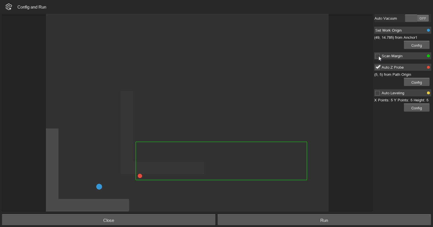
- There should appear a preview of the GCODE, check the path and choosen tools. Then use the Gear-Icon on the bottom left to start the milling.
 ALWAYS CHECK THE PATH ON THE BOTTOM!!
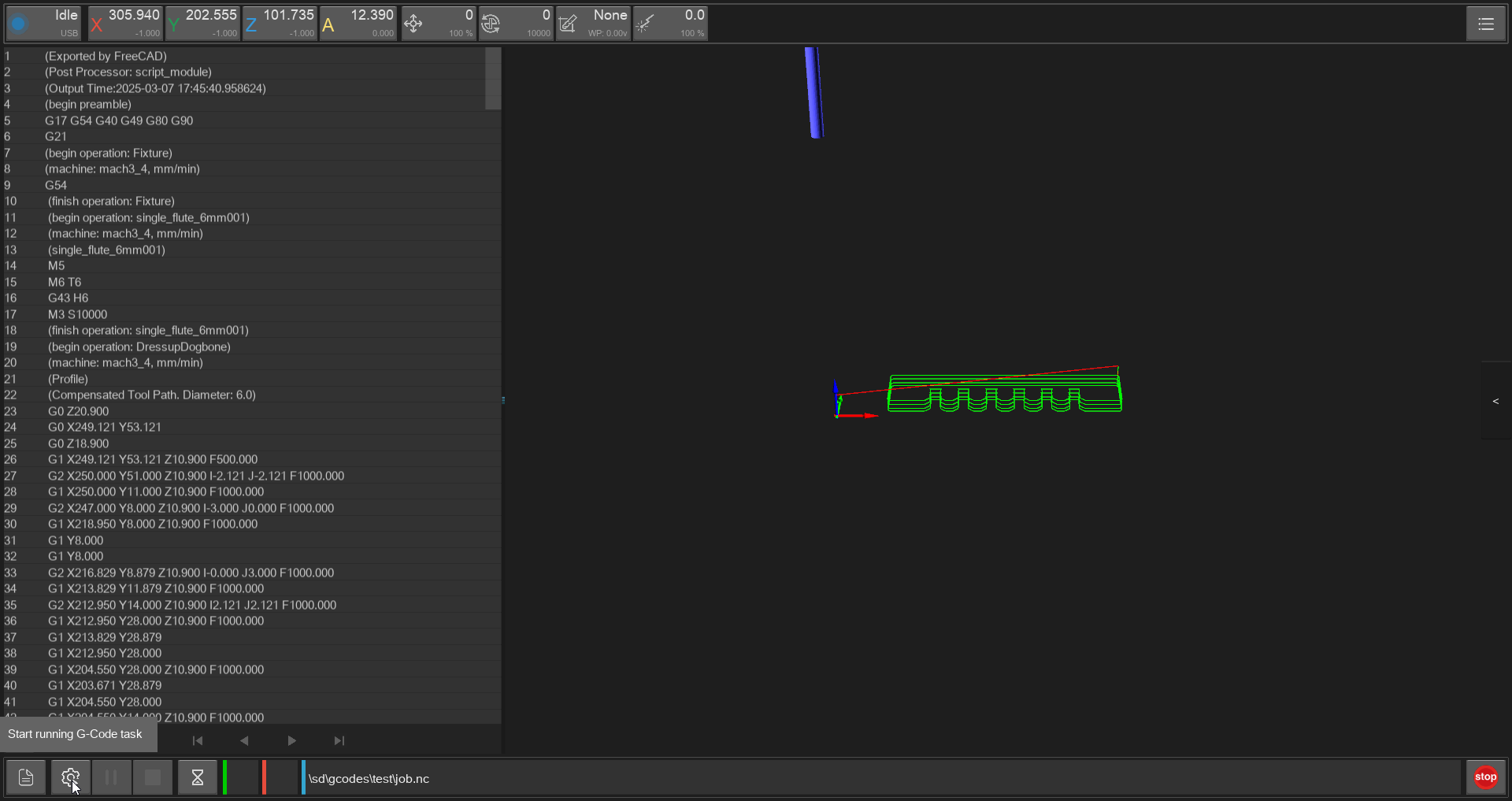
Then here deactivate 'Scan Margin' and if allready done 'Auto Z Probe' and press 'RUN'.
See also
Tips and Tricks
Maintenance
Troubleshooting
Carvera Makera
Machine coordinates in the software constantly increase
- just restart the machine, ALSO DISCONNECT THE MACHINE FROM USB and then restart the software
Toolchanger often failes on changeing the tool
- happens because the tools is not correctly inserted and can be solved by bending the metal clamp inwards
TODO IMAGE
Lasercutter
An 80W CO2 Laser for cutting and etching/engraving Materials like Wood/Plastics/Stone/Metall
Specification/Materials
Machine Parameters
- Kerf: 0.1mm
- Focus length 15mm
Specifications
- possibly the vevor 80W co2 lasercutter
- 80 W CO2 Laser
- 700mm x 500mm Working Area
- 1000mm/s max speed
- 0.01mm precision
- 1000 DPI resolution
- 644XS Controller
- RD Works Software
Materials
CUTTING
- wood
- plywood/composite woods
- MDF/engineered wood
- Paper/card stock
- cardboard,carton
- cork
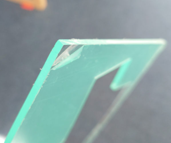
- acrylic/lucite/plexiglas/pmma
- don't remove the bottom 'green' foil
- because it blocks the reflections/dispersion of the laser beam which could get reflected to the material and then melt it

- thin (<1mm) polycarbonate sheeting
- derlin (POM)
- kapton tape (polyimide)
- mylar
- solid styrene
- depron foam
- gator foam
- cloth/felt/hemp/cotton
- leather/suede
- magnetic sheet
- NON-CHLORINE-containing rubber
- teflon(ptfe)
- carbon fiber mats/weave (without epoxy)
- coroplast ('corrugated plastic')
ETCHING
All above and additionaly (CAN NOT BE CUT but etched):
- Glass
- Ceramic tile
- anodized aluminum
- painted/coated metals
- stone,marble,granite,slate,soapstone,onyx
Safety Instructions
General
- ALWAYS SETUP AND TURN ON the gas extractor and chiller (on the left side both switches)
- always wear safety gear (glasses)
- you don't want you material to melt -> higher chance for FIRE when stringing
- check the gas/steam emission when cutting
- if to much gas/steam, adjust the settings (less power or more speed)
- know where the fire extinguisher is
- never leave laser while lasering and check from time to time/no headphones
No Go Materials
Don't use following materials:
| Material | DANGER!! |
|---|---|
| PVC (Poly Vinyl Chlorid)/vinyl/pleather/artifical leather | Emits chlorine gas when cut ruin optics and corodes metal! |
| Thick (>1mm) Polycarbonate/Lexan | Cuts very poorly, discolors, CATCHES FIRE!!! long stringy clouds on cutting -> will ruin optics and mechanics |
| ABS (Acrylonitrile butadiene styrene) | Melts instead of vaporize / Hydrogen Cyanide Gas on cutting -> UNSAFE |
| HDPE/ milk bottle plastic | Catches fire and melts |
| PolyStyrene/PolyPropylene Foam | CATCHES FIRE VERY EASILY! |
| Epoxy | can't cut -> burns/ smokes Cyanide!! |
| Fiberglass | Emits fumes (glass can only be etched and epoxy only smokes) |
| Coated Carbon Fiber | emits noxious fumes!! (carbon fiber can be cut, but not when coated) |
| Any Food | Not food-safe -> many toxic gases where in the laser for a longer time |
| Material With Sticky Glue Backing | Coats/ cracks lens when CUT; also hard to remove from the lens! |
How to use
0. Wear Safety Gear and Setup Suction
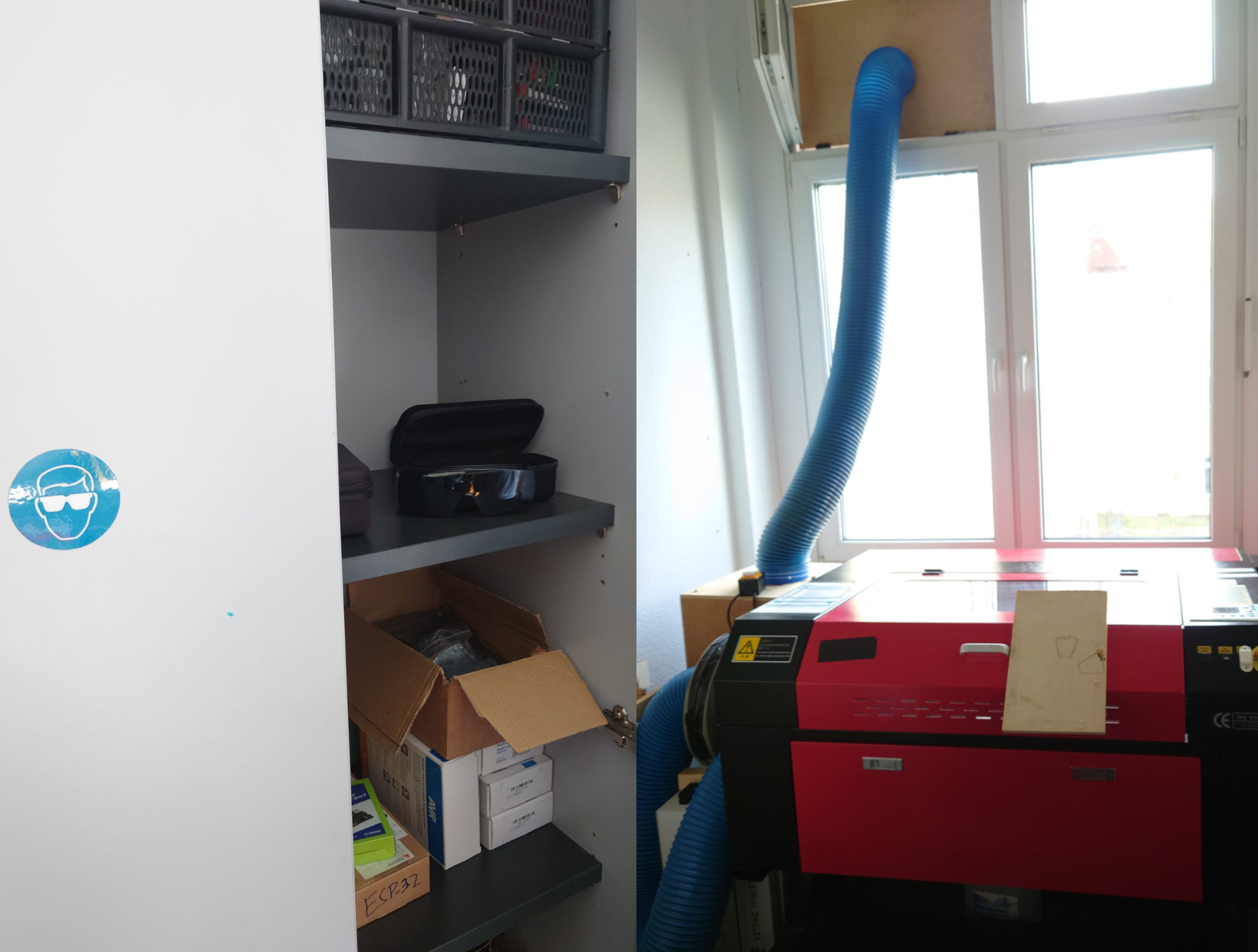
Safety glasses are found in the cabinet next to the door, DON'T TOUCH THE GLASSES ON THE PROTECTIVE SIDE.
Before starting, install the tube to the upper window like here:
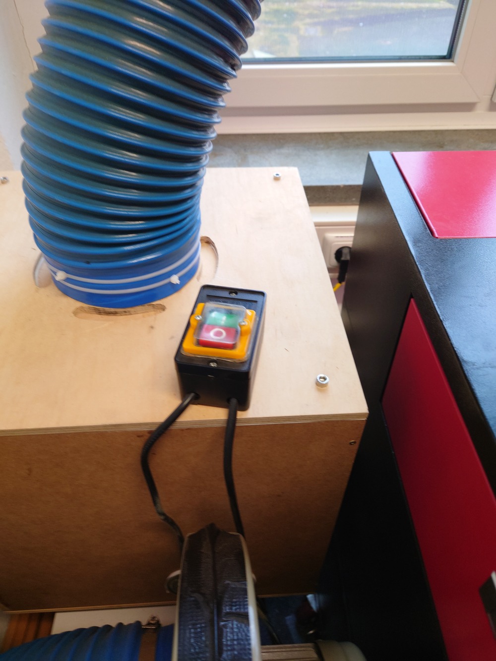
1. Turn on Suction, Cooling and Laser
First turn on the suction:
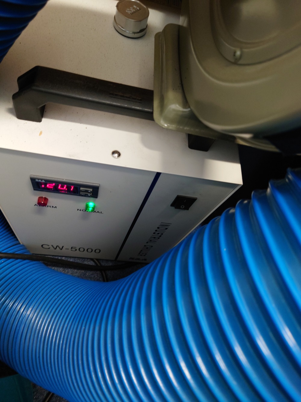
Then the cooling for the laser (behind the blue tube):
And afterwards the laser itself. It is on the bottom right side of the laser with the round switch (labeled 'main switch'):
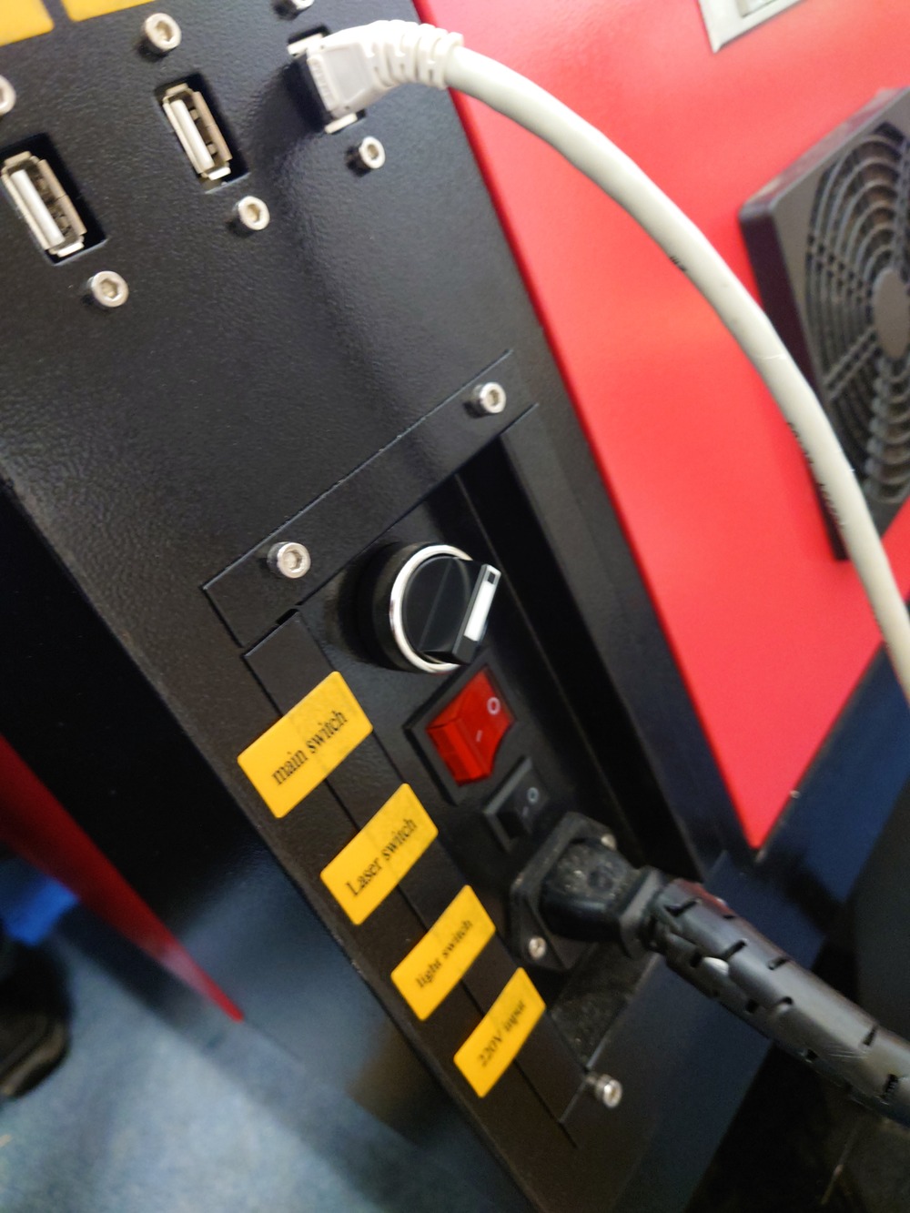
Also on the side panel there is the switch for the laser tube and the light switch. Only turn on the laser itself ('Laser switch') when needed.
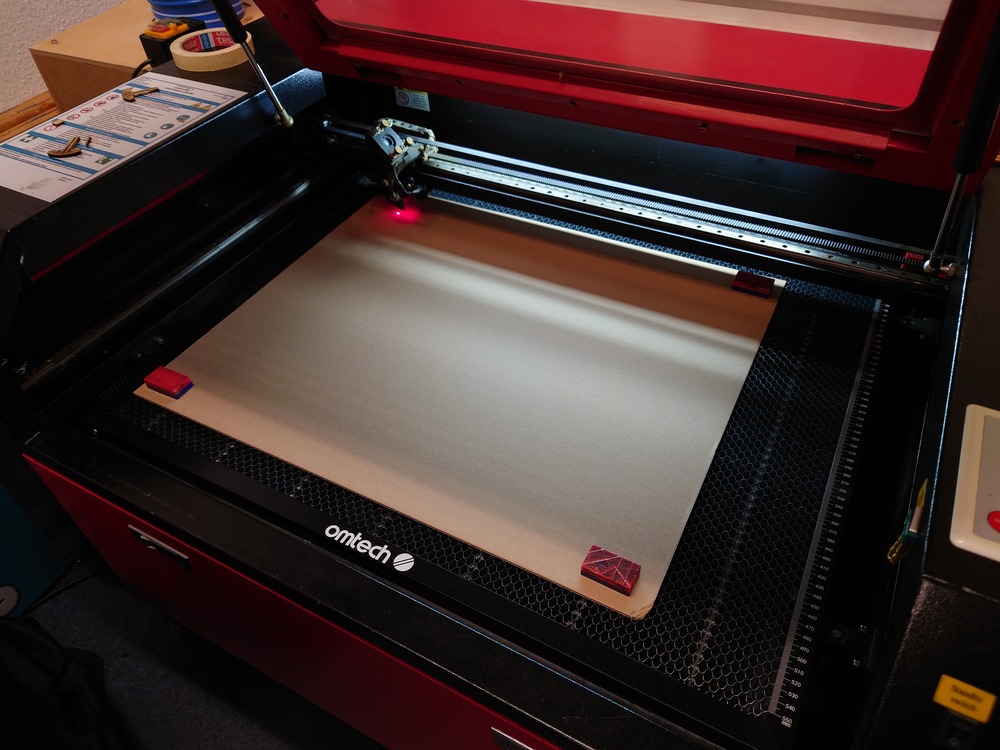
2. Fasten Material
Next place the material and if its not heavy/flat enough, use the red/blue magnets and fixture onto the table.
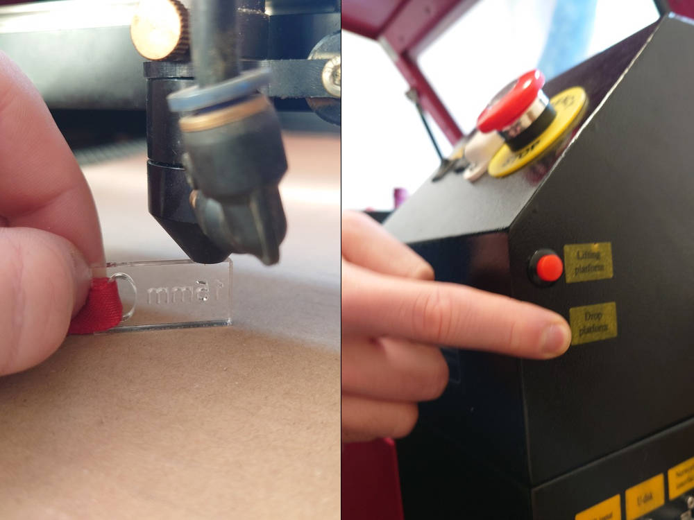
3. Adjust Focus
For a precise cut you have to set the focus onto the surface of the material. Use the top right side buttons for lift/lower the workplate.
Then use the focus-piece and place it between material and laser. Caution! Two focus-pices are available: 15mm and 20mm Use the 20mm pice
To find the right settings you can laser this test array to dial in the parameters.
4. Set Origin
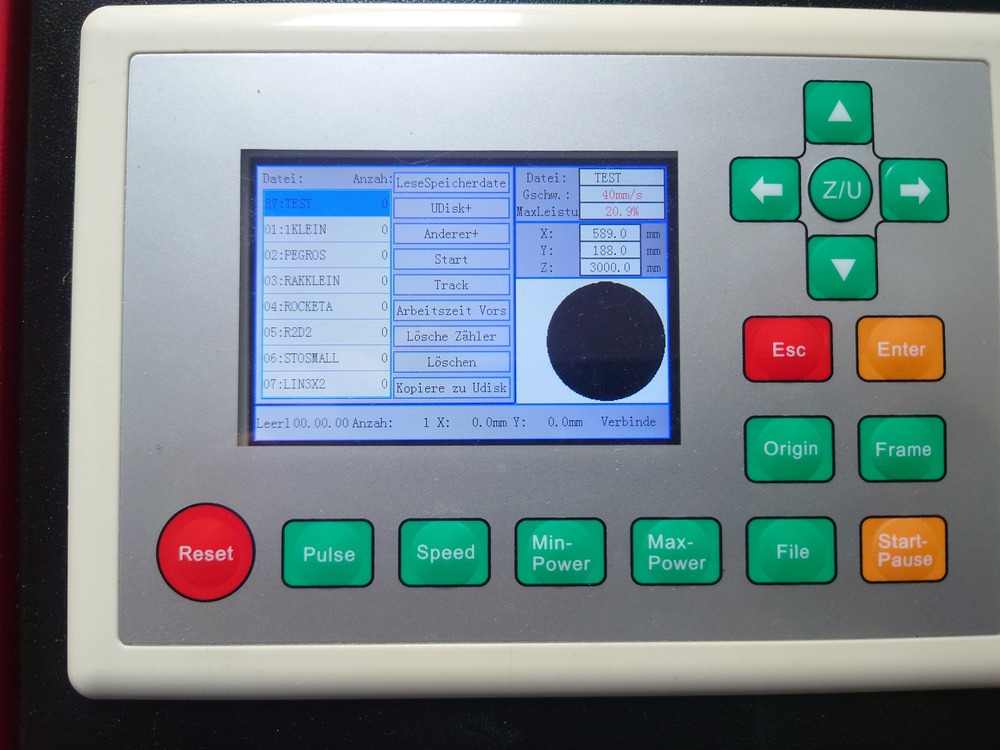
Then use the control panel on top of the laser to set the origin of your work by using the arrow keys to move and the 'Origin' button to set it.
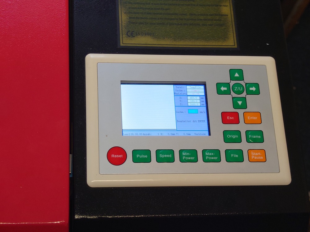
Control Panel Buttons
Reset : restarts machine controller, also homing on restart, abrupt stop
Pulse : aktivates the laser for a short period with the currently set power
Speed/Min-Power/Max Power : sets the current Speed/Max-/Min-Power of the machine; after choosing the value with the arrow keys above, press 'ENTER'
File : used for selecting uploaded files, shows a preview on the right side of the panel, for selecting, use again the arrow keys and 'ENTER', for exiting 'ESC'
Origin : sets the current position as the origin
Frame : If a file is selectet, drives the outline of the file
Start/Pause : start/pause currently selected file/operation
Esc : Used for stopping the currently paused operation gracefully
When nothing is selected the Arrow Keys are used for X/Y-Movement with the currently set speed.
5. Prepair File to Cut/Etch in RDWorks
Open RDWorks 
Here you can import ONLY DXF files on the top left Menu File->Import.
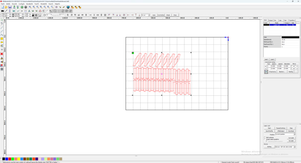
On the bottom left side, you can assign new layers with the colors for your components when needed. (Yes, only as many layers as there are those colors -.-)
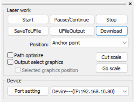
The importent settings are on the right side:
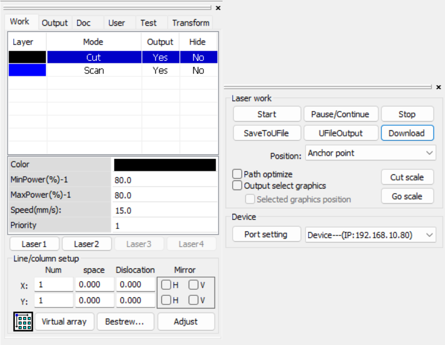
Then on the top right panel (left on the picture) are the settings for layers, the operation, speed and power for each of them. And on the bottom right (right in the picture) you can select the choosen position, port/address of the laser and can control it here (more later)
The selected one can be edited quickly with the fields below or with Double Click edit the advanced settings for the selected layer. Ensure in the column 'Output' is a yes for all layers.Here you can import ONLY DXF files on the top left Menu File->Import.
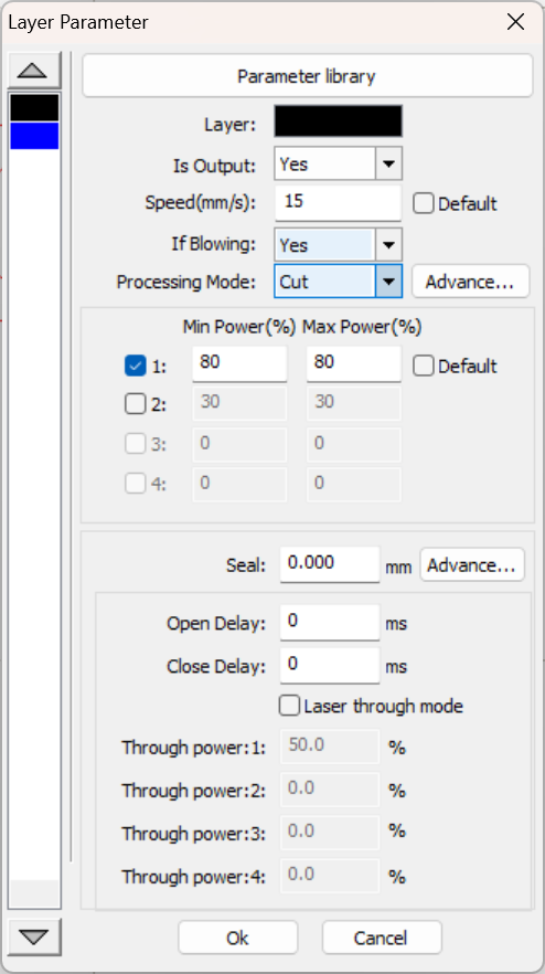 |
In the top you have a small parameter library with predefined parameters that should usually work. Then Speed is very important and depends heavily on the material/operation. Then the operation mode, where - Cut : Drives along the path of the vector graphic - Scan : filles the area the vector graphic spans with many parallel lines - TODO : TODO - TODO : TODO Then Power is also very important and also depends on material and operation. TODO |
6. Start Cutting/Etching
For starting you need the bottom right settings:
0. Origins in RDWorks
One important field is the Position, where you set the origin the machine should use.
But it's only applied when starting from the software
| Position | Meaning |
|---|---|
| Absolut Coordinate | Uses absolute coordinates from the software, so the machine zero as reference point |
| Anchor Point | Uses the position of the origin setting on the machine |
| Current Position | Uses current position of the laser, not origin |
| Machine Origin | ???? |
When starting from the machine, the origin of the machine is always used.
1. Start directly in RDWorks
Then to start lasering, Start directly uploads and starts the file.
2. Upload to Laser and start
You can also use 'Download' to upload the file to the machine.
Then on the machine you can re-adjust the position and check the outline it with the 'Frame' button.
To load the file, press File then select it and use it with Enter
Tips and Tricks
- when you want to align something precisely, cut out the outline of the piece in Cardborad and place the piece you want to align into it
Maintenance
Troubleshooting
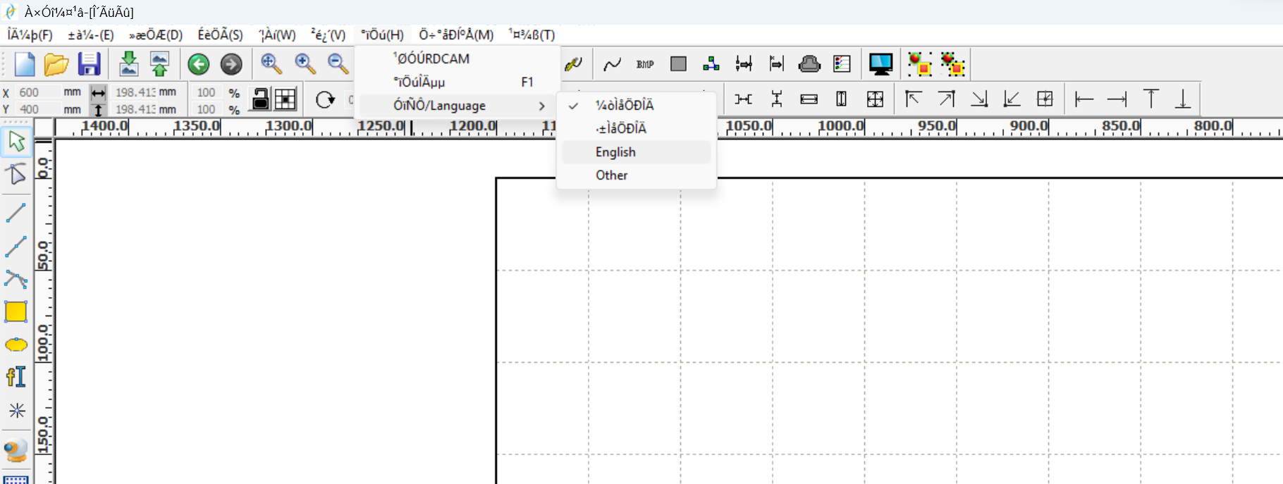
Software: RD Works Errors
Wierd Language
If RD Works menues are displayed in a wierd way.
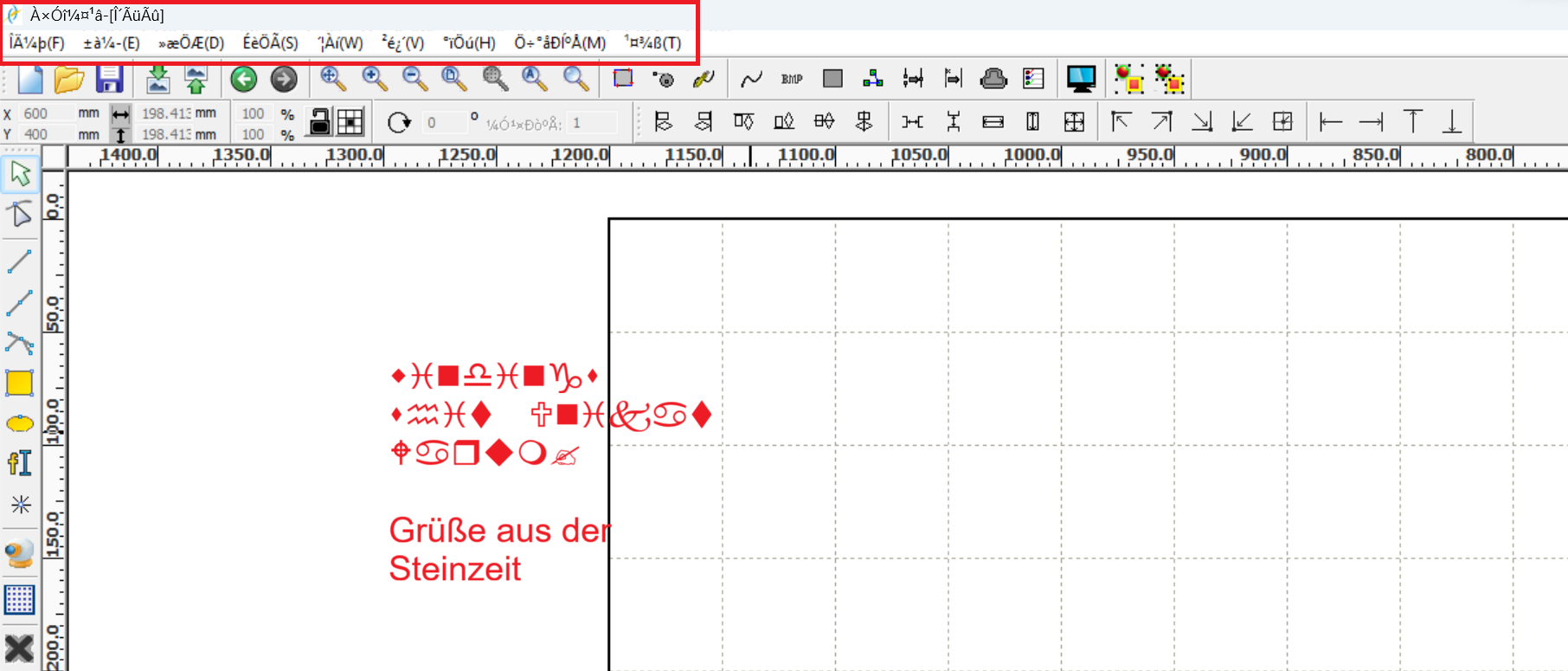
Change the language settings:
Hardware: Machine Errors
Engraving Accelerartaion Issue
Machine error (German): Nicht genug erw. Sper Bitte "Esc"
Machine error (English):
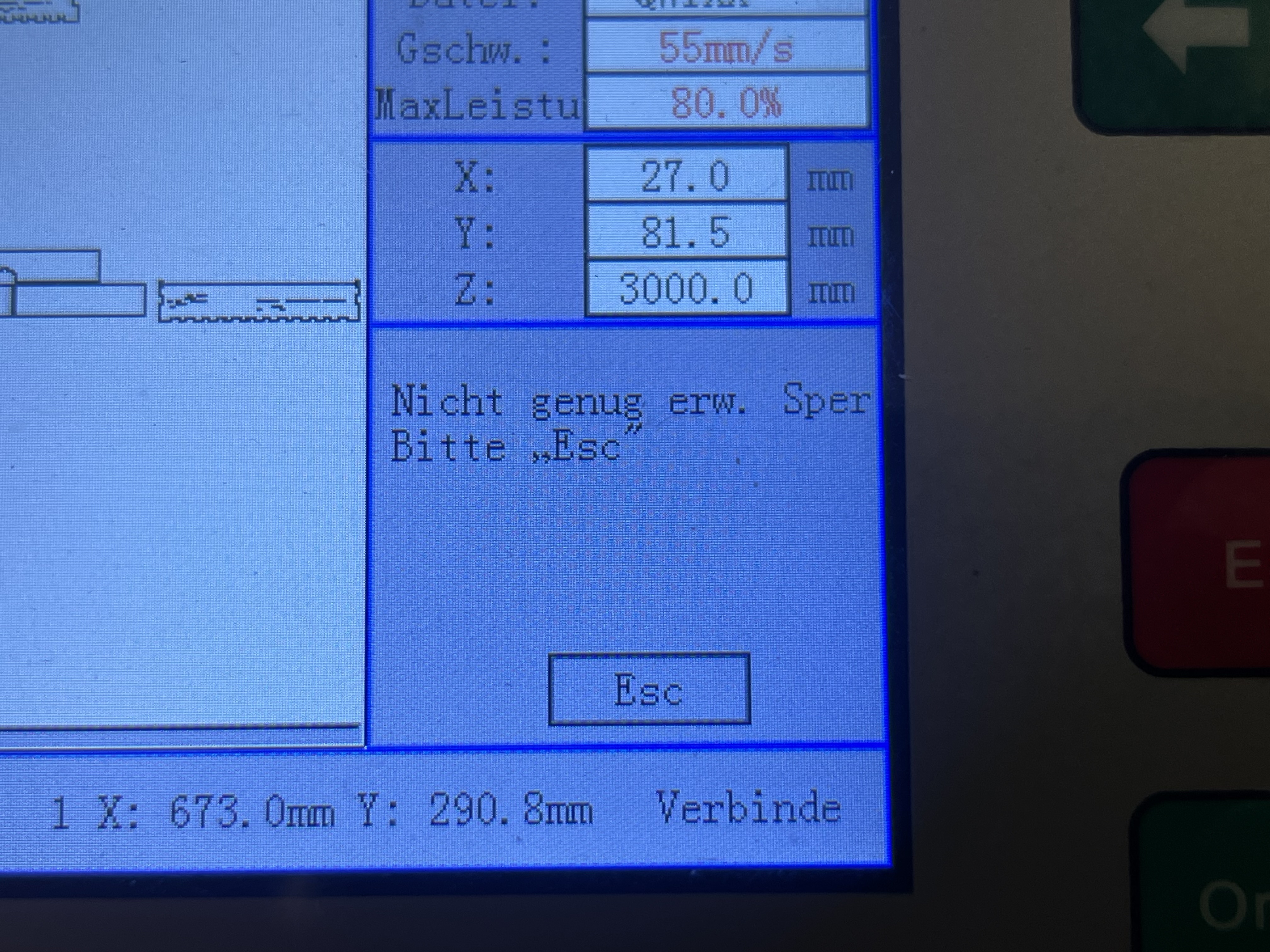
When engraving elements are placed very close to the edge of the work area, the laser head cannot accelerate/decelerate in the X direction enough. The head needs some space to speed up or slow down.
Solution: Place the engraving pattern farther away from the edge of the work area. Alternatively, move the origin closer to the center of the machine bed.
A more precise explanation can be found here:
Forum - Fablab Luebeck (German)
Frame solp/engrave slop - Youtube (English)
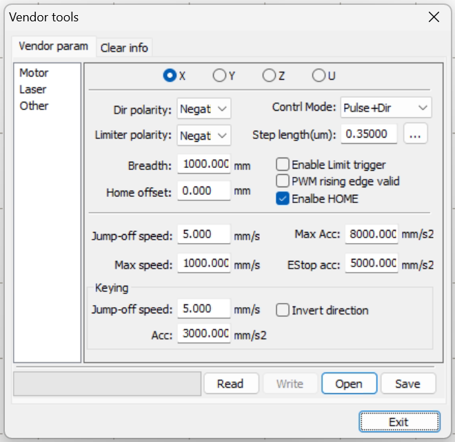
Enter Vendor Settings
Use RD Works to enter and change the controller's vendor settings. Go to "File" > "Vendor Settings," and enter the password for the motherboard.
Vinylcutter
A small desktop cutter used for smaller, mostly flat material.
Usefull Links:
An industry rolling cutter user for really big materials roll.
Specification/Materials
Silhouette Curio 2
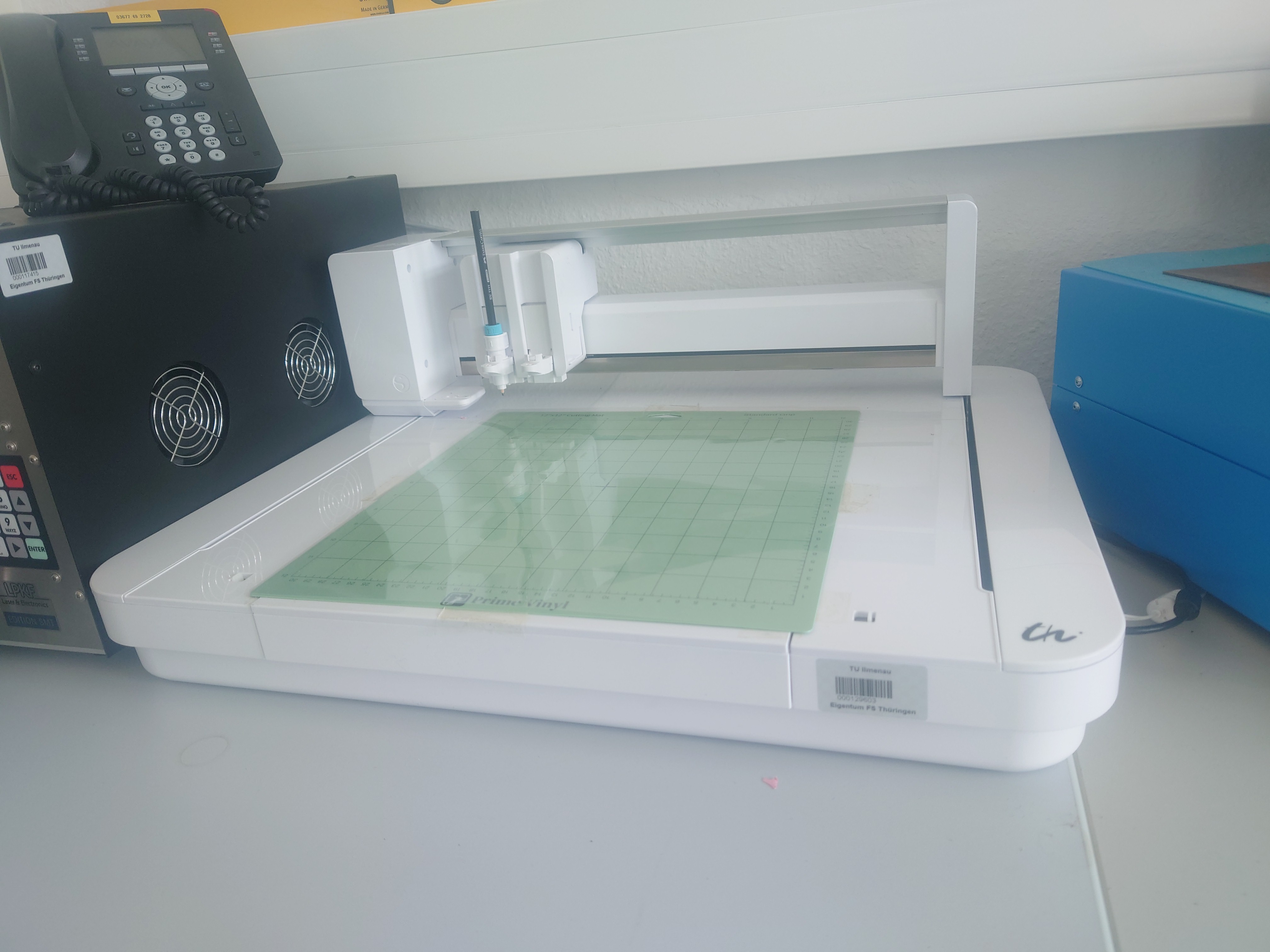
Features
- Electrostatic cutting surface (but cutting mat makes it easier)
- Automatic Tool detection (not on the selfmade of course)
- Measure Material thickness automatically
- USB/Bluetooth
- 2 Tool Holders
Specifications
- 30 x 30 cm Cutting Area
- Max Material Thickness: 20mm
- Max Cutting Thickness: 3mm
Tools/Heads
TODO
Summa S3 T75
TODO
Specifications
- 76mm roll diameter (needs adapters for shorter ones
- 500mm roll length
How to use
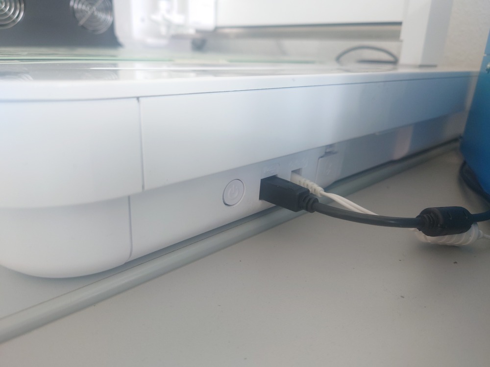
1. Turn on
Press the power button on the right side for a few seconds:
2. [Optional] Insert tools
Next choose your tool you want to use, currently there are:
Tools
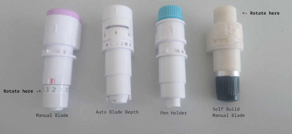
| Tool | Feature |
|---|---|
| Curio Manual Blade | Tool with blade, where the tool-depth needs to be adjusted manually - adjustment and disamble by rotating the bottom scale |
| Curio Auto Blade | Tool with blade, where the tool-depth can be adjusted with the software, it then drives into the left side of the machine and presses mechanically the tool down - press the bottom to manually set the tool-depth |
| Curio Pen Holder | Tool for a penn, which can be tightend on the top, an the top part can be changed for different pens |
| Self Build manual tool | Self printed manual tool, like the above, but to adjust it, rotate on the top - rotate the bottom to change the blade |
All tool belong into SLOT 1.
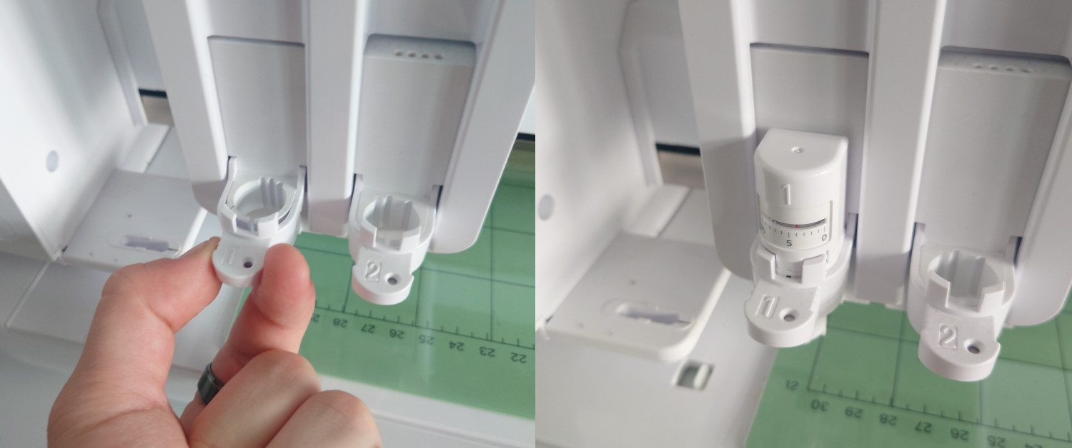
Load A Tool
Then you can use the 'Tool Change' button to move the machine to the front or back (arrow keys) and insert the tool.
Then to change the tool, pull on the latch, place the tool and push on it.
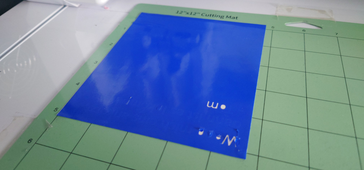
3. Place Material
Before placing the material:
- remove the protective film placed on the cutting area (place it back when finished)
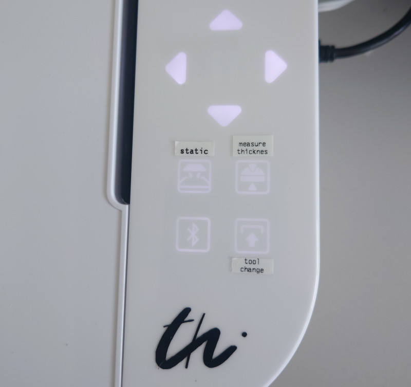
- activate the electrostatic bed with the 'static' button, it takes a while to charge up the material
Then optionaly change the/place a cutting mat if your material is not flat enough/bends up. (Cutting mat is optional but especialy very bend materials hold better on it)
It should be flat and stuck on the bad, so not easy to move away.
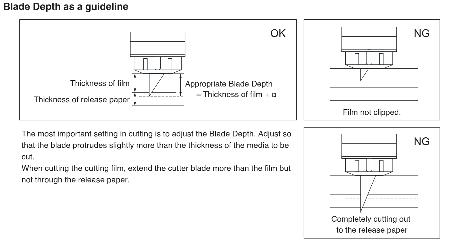
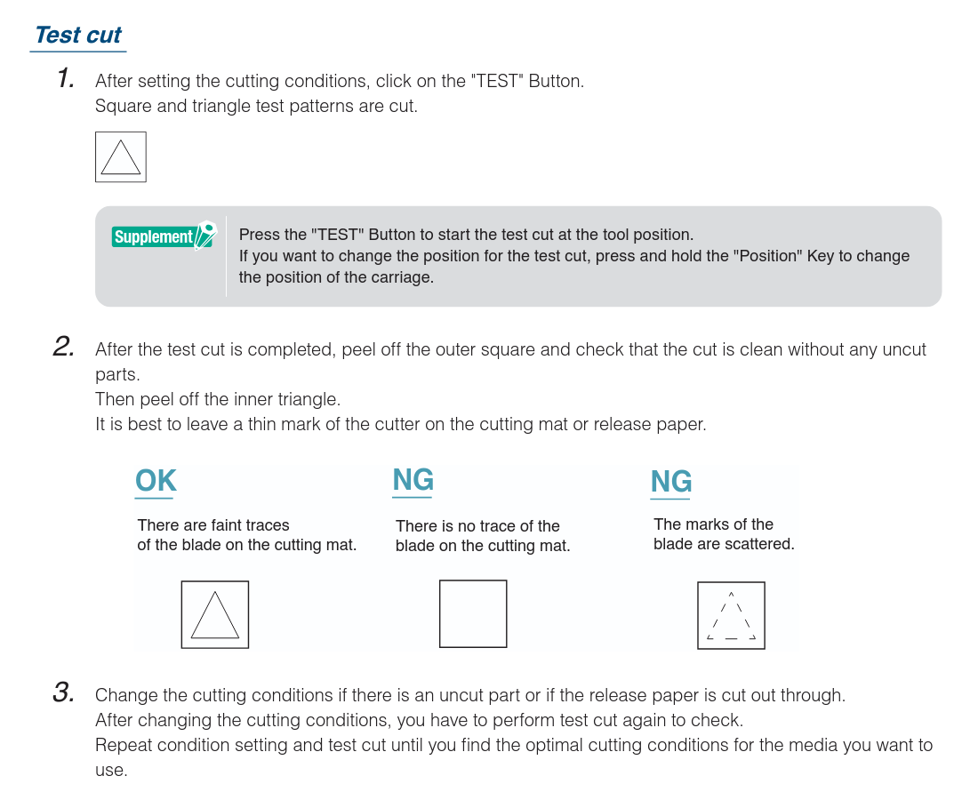
4. Make a test cut
Blade Depth Guideline
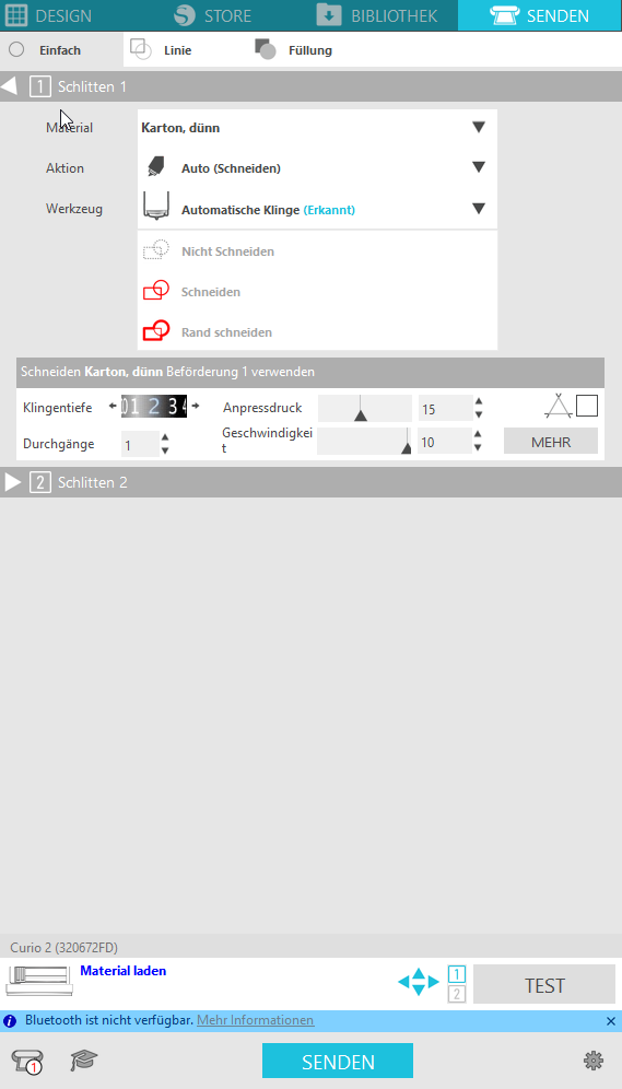
Adjust the settings
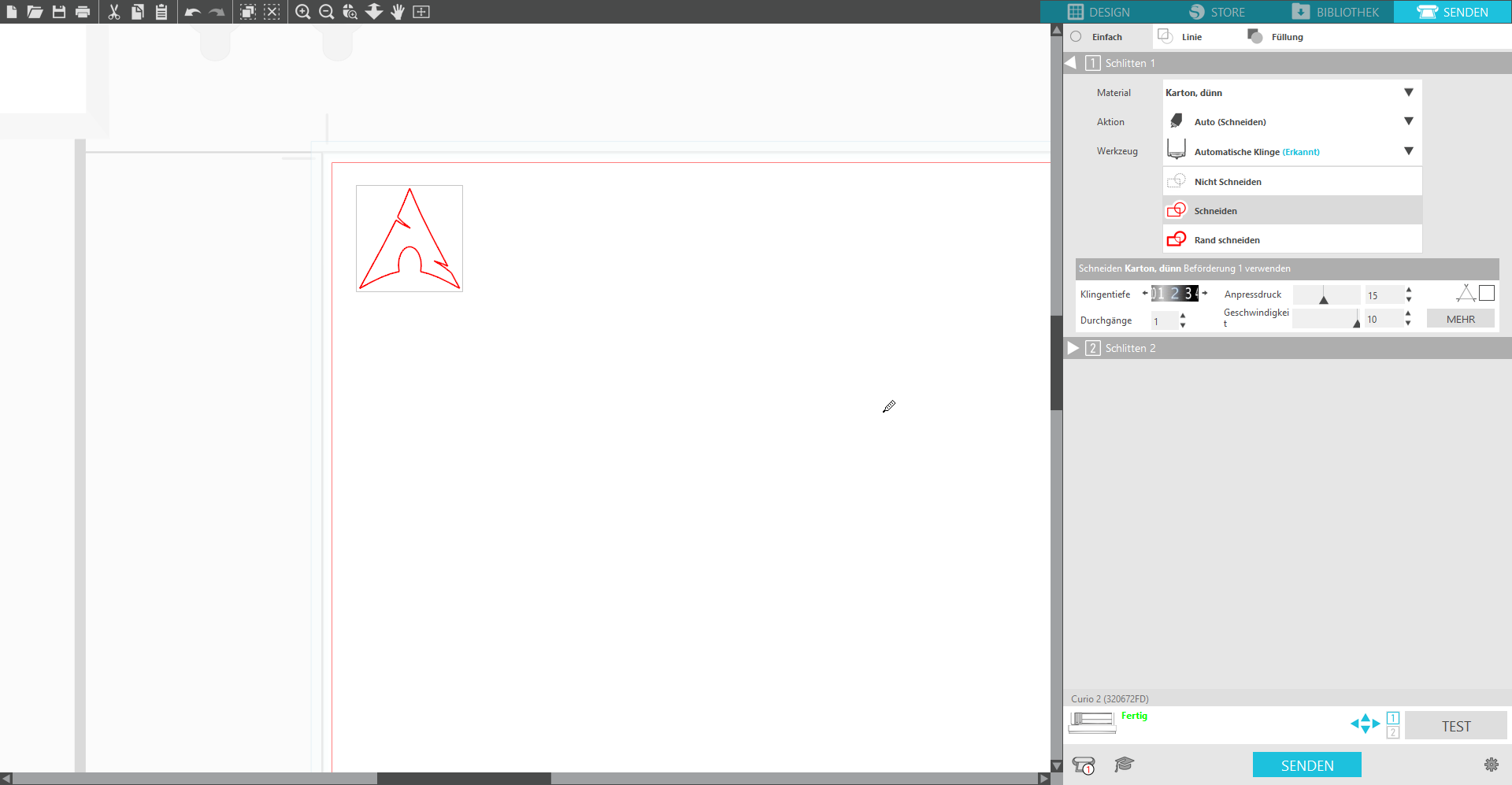
Open ![]() Silhouette Studio and go to the top right tab 'SENDEN' (send).
Silhouette Studio and go to the top right tab 'SENDEN' (send).
There you can adjust the Settings for the tool.
The most important part it the seconds box from the top 'Schneiden' (cut).
| Description | Image |
|---|---|
| 'Klingentiefe' (cutting depth) - is only used for the auto knife depth tool, the other ones need to be adjusted manually, but THE MOST IMPORTANT 'Anpressdruck' (contact preasure) - is the preasure/z offset used to go into the material -higher for harder materials, lower for softer to not rip it' - not that important 'Durchgänge' (rounds) - the number of repititions 'Geschwindigkeit' (speed) - i guess the percentage from max speed - lower for more complex structures to cut |
 |
Make the cut
Drive to the position you want to test with the arrow keys on the machine.
MEASURE THE THICKNESS with the botton on the machine.
- When you use reflective media,apply masking tape and then detect the thickness at that position.
- The sensor is attached to the bottom of the Tool Holder 2.
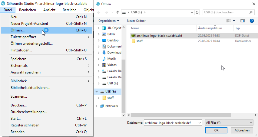
5. Import and Prepair in software
- save your garphic in DXF R12 format and import it in Silhouette Studio in 'File'->'Open...' ("Datei"->"Öffnen...")
- make sure, it has the right size (the software is not that nice for adjustments afterwards
- then go to the 'Send' (Senden) tab and adjust positioning and settings
For the operations:
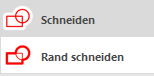
- Cut ("Schneiden") means cut along ALL paths
- Cut Outline ("Rand schneiden") means cut ONLY OUTER PATHS, so only arround your image
TODO Pass Markings
6. Start cutting
- and if everything is allright, start cutting by sending ('SENDEN')
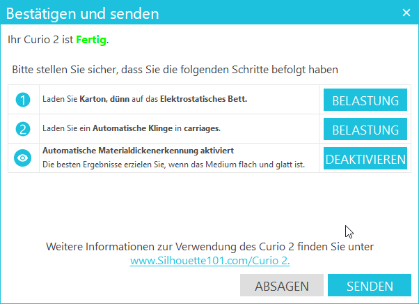
Here it shows just a step by step guide plus the setting for material depth perseption. If you did it before, just press deactivate ('DEAKTIVIEREN') to turn it of.
Then again press send ('SENDEN')
Tips and Tricks
Maintenance
Troubleshooting
3D Printer
Prusa Core One (2x)
A small enclosed FDM printer usable for almost all materials.
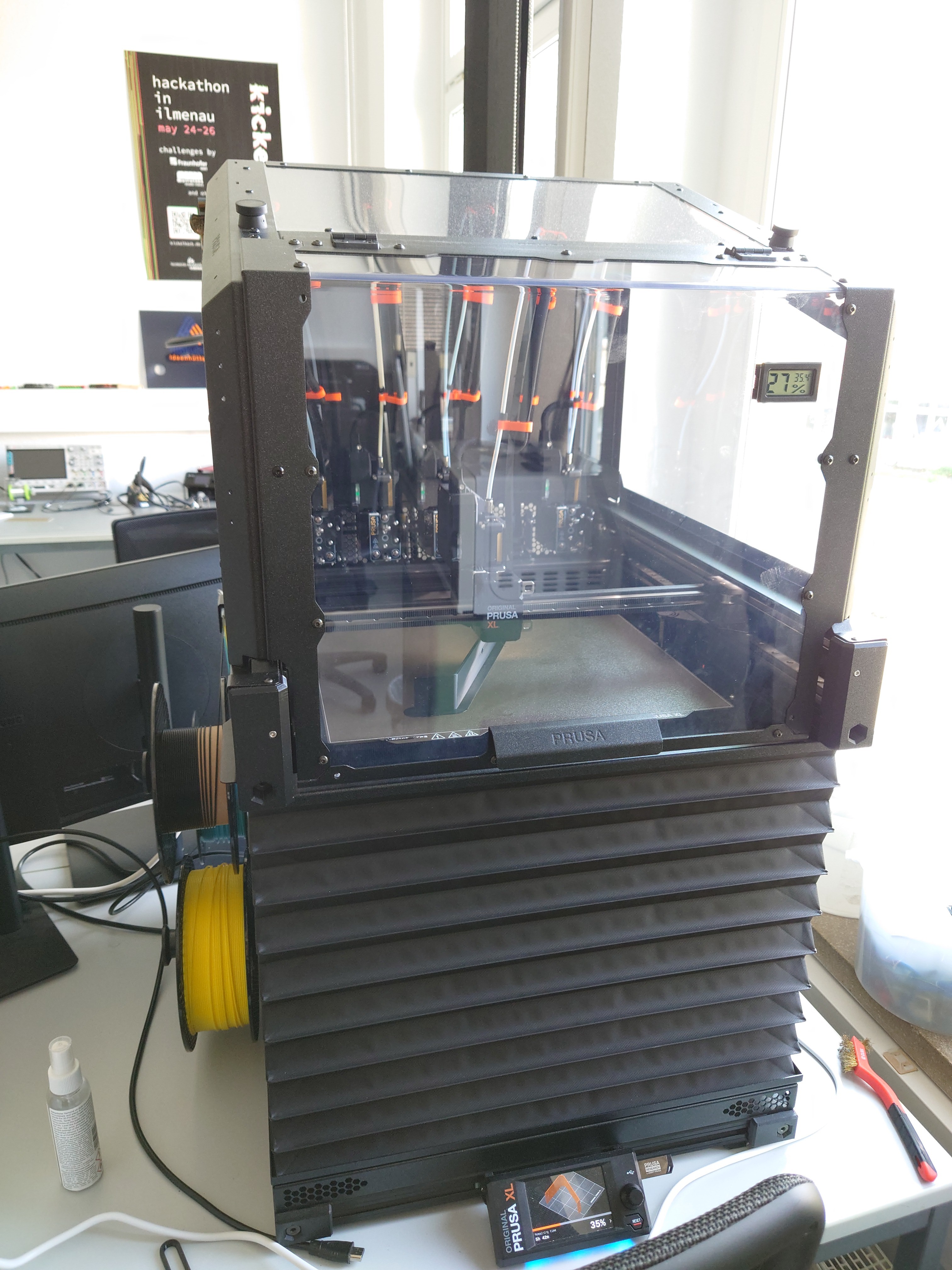
Prusa XL
A big enclosed FDM printer usable with an multi material unit which can print with up to 5 different materials
Eleego SLA Printer
A small SLA Printer usable for very small, precise and robust prints, but a more toxic process/materials
Specifications/Materials
How to use
Tips and Tricks
Maintenance
Troubleshooting
French Cleat
French Cleats - Laser
French Cleats currently used:
- WallChiselHolder
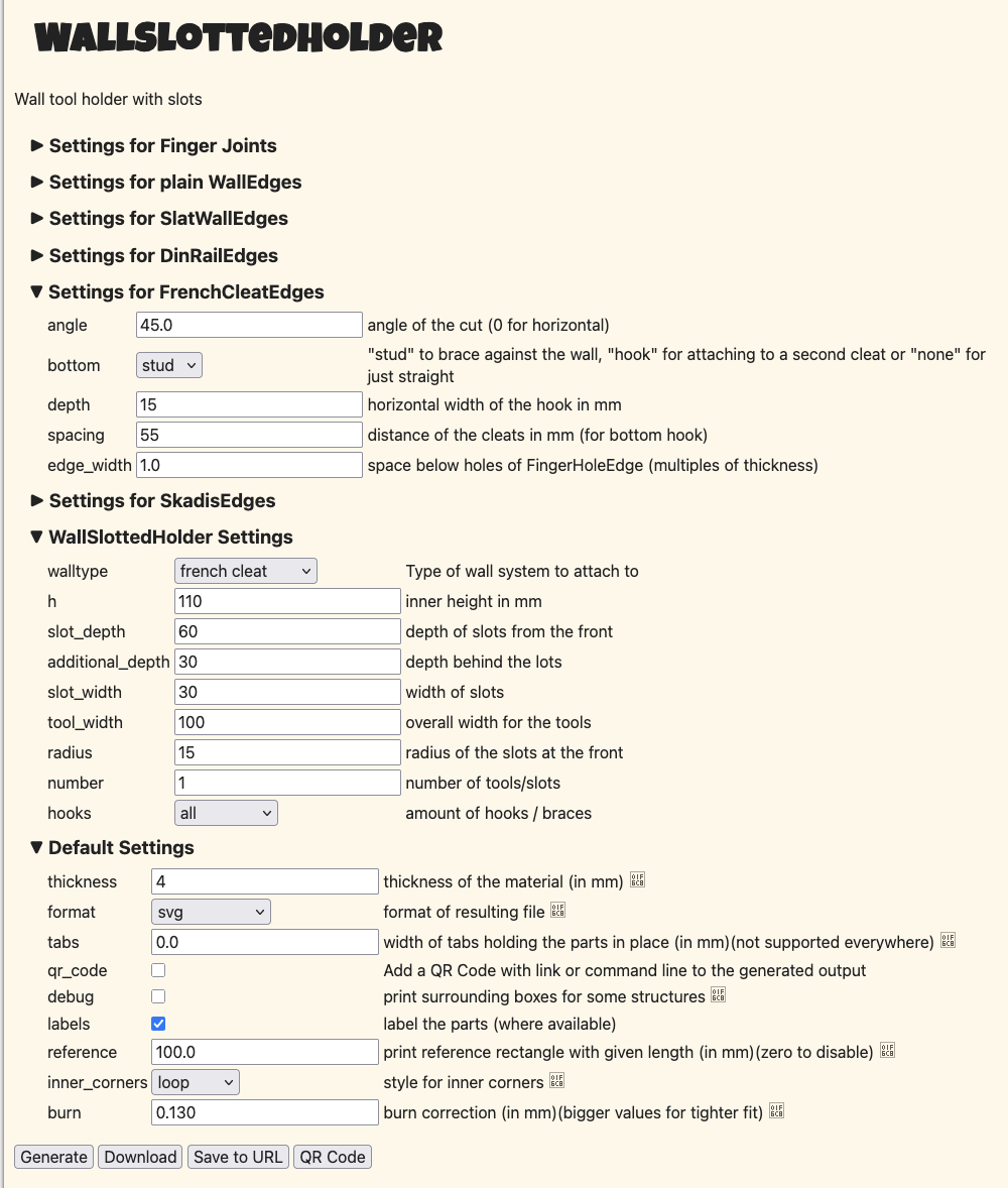
- WallSlottedHolder
- settings:

- settings:
- {work in progress} WallCaliper